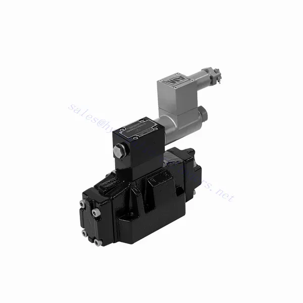
GWEH Series Explosion-proof Directional Hydraulic Valve
GWEH Series Explosion-proof Directional Hydraulic Valve
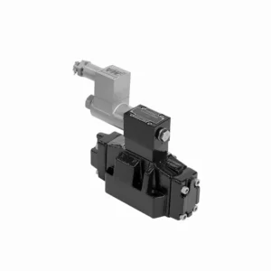
The GWEH series explosion-proof directional hydraulic valve is an innovative solution designed to provide optimal safety and precise control in hydraulic systems operating in hazardous environments. With its explosion-proof features, reliable performance, and advanced functionalities, this valve offers enhanced safety measures, efficient fluid flow control, and compatibility with various industrial applications.
The GWEH series explosion-proof directional hydraulic valve is a reliable and efficient solution for industries operating in hazardous environments. With its explosion-proof design, precise directional control, versatility, and high performance, this valve ensures safety and control in hydraulic systems. Following the recommended usage methods and adhering to regular maintenance practices, the GWEH series valve delivers safe and efficient operation in explosive atmospheres. Upgrade your hydraulic system with the GWEH series explosion-proof directional hydraulic valve and experience enhanced safety, optimal fluid flow control, and reliable performance.
GWEH Series Explosion-proof Directional Hydraulic Valve Key Characteristics:
- Explosion-proof Design:
- The GWEH series valve is engineered with a robust explosion-proof design, ensuring safe operation in environments containing flammable gases or dust.
- It complies with stringent safety standards and certifications, minimizing the risk of ignition and ensuring the safety of personnel and equipment.
- التحكم الاتجاهي:
- This hydraulic valve provides precise directional control of fluid flow, allowing for the activation and deactivation of specific hydraulic actuators.
- It enables smooth and reliable operation of various hydraulic functions, such as cylinder extension and retraction or motor direction changes.
- التنوع والتوافق:
- The GWEH series valve is highly versatile and compatible with various hydraulic systems and applications.
- It can seamlessly integrate into industrial machinery, mobile equipment, and automation systems operating in hazardous environments.
- أداء عالٍ:
- With its advanced design and high-quality construction, the GWEH series hydraulic valve delivers exceptional performance and reliability.
- It ensures consistent and precise control over fluid flow, contributing to efficient and optimized system operation.
GWEH Series Explosion-proof Directional Hydraulic Valve Parameter:
NG10
| Working pressureP,A,B | حاجِز | 315 | |||||||||
| ميناء تي | With external pilot oil drain | حاجِز | 315 | ||||||||
| With internal pilot oil drain | حاجِز | 210 | |||||||||
| المنفذ Y | With external pilot oil drain | حاجِز | 210 | ||||||||
| الحد الأدنى لضغط التحكم | مع إمداد زيت الطيار الخارجي
مع إمداد زيت الطيار الداخلي (not apply to C, Z, F, G, H, P, T, V) |
حاجِز | 3-position valve 10 | ||||||||
| Spring-return 2-position valve 10 | |||||||||||
| Hydraulic-return 2-position valve 7 | |||||||||||
| مع إمداد زيت الطيار الداخلي ( apply to C, Z, F, G, H, P, T, V) |
حاجِز | 4.5 | |||||||||
| Max. control pressure | حاجِز | 250 | |||||||||
| سائل | زيت معدني، إستر الفوسفات | ||||||||||
| نطاق درجة حرارة السائل | درجة مئوية | -30 إلى +80 (أختام NBR | |||||||||
| -20 إلى +80 (أختام FKM) | |||||||||||
| نطاق اللزوجة | مم2/ث | 2.8 إلى 500 | |||||||||
| Controlled quantity in commutating process | cm3 | 3-position valve 2.04 2-position valve 4.08 | |||||||||
| Switching times (= Valve switching time from the neutral position to the switched position)(DC ) | |||||||||||
| Control pressure | حاجِز | 70 | 140 | 210 | 250 | ||||||
| 3-position valve | آنسة | 65 | 60 | 55 | 50 | ||||||
| 2-position valve | آنسة | 80 | 75 | 70 | 65 | ||||||
| أوقات التبديل (= وقت تبديل الصمام من الوضع المحول إلى الوضع المحايد) | |||||||||||
| 3-position valve | آنسة | 30 | |||||||||
| 2-position valve | آنسة | 35 | 40 | 30 | 35 | 25 | 30 | 20 | 25 | ||
| Flow of shortest switching time | لتر/دقيقة | حوالي 35 | |||||||||
| موضع التثبيت | HC, HD, HK, HZ and HY of hydraulic return shall be installed horizontally. The rest are arbitrary | ||||||||||
NG16
| تحديد | G-..WEH16../6B2.. type | |||||||
| Working pressureP,A,B bar | 350 | |||||||
| ميناء تي | مع قضيب تصريف زيت الطيار الخارجي | 250 | ||||||
| مع قضيب تصريف زيت الطيار الداخلي | 210 | |||||||
| Hydraulic-centering 3-position valve With internal pilot oil drain is impossible | ||||||||
| المنفذ Y | مع قضيب تصريف زيت الطيار الخارجي | 210 | ||||||
| الحد الأدنى لضغط التحكم | With external pilot oil supply bar
With internal pilot oil supply bar |
3-position valve 14 | ||||||
| صمام رجوع زنبركي ثنائي الوضع 14 | ||||||||
| Hydraulic-return 2-position valve 14 | ||||||||
| مع إمداد زيت الطيار الداخلي ( apply to C、Z、F、G、H、P、T、V) bar |
When applying back pressure valve or the flow is large, enginery of spool valve is 4.5 bar as C、Z、F、G、H、P、T and V | |||||||
| أقصى ضغط تحكم بالبار | 250 | |||||||
| سائل | زيت معدني، إستر الفوسفات | |||||||
| نطاق درجة حرارة السائل ℃ | -30 إلى +80 (أختام NBR | |||||||
| -20 إلى +80 (أختام FKM) | ||||||||
| Viscosity range mm2 /s 2 | 2.8 إلى 500 | |||||||
| تبديل حجم زيت الطيار | ||||||||
| -Spring-centering 3-position valve cm3 | 5.72 | |||||||
| -2-position valve cm3 | 11.45 | |||||||
| * أوقات التبديل (= وقت تبديل الصمام من الوضع المحايد إلى الوضع المحول) (التيار المتردد والتيار المستمر) | ||||||||
| شريط ضغط التحكم | 50 | 150 | 250 | |||||
| – Spring-centering 3-position valve ms | 65 | 60 | 58 | |||||
| – 2-position valve ms | 65 | 55 | 50 | |||||
| *أوقات التبديل (= وقت تبديل الصمام من الوضع المحايد إلى الوضع المبدل) | ||||||||
| – Spring-centering 3-position valve ms | 40 | |||||||
| – 2-position valve ms | 45 | 35 | 30 | |||||
| موضع التثبيت | C,D,K,Z,Y Type hydraulic-return valves are installed horizontally, the rest can be installed arbitrarily。 | |||||||
| Flow of shorter switching time L/min | حوالي 35 | |||||||
| Weight of the valve kg | about 10.6 | |||||||
NG25
| تحديد | G-H-…WEH25../6B2… type | |||||||||
| Working pressureP,A,B bar | 350 | |||||||||
| ميناء تي | مع قضيب تصريف زيت الطيار الخارجي | 250 | ||||||||
| مع قضيب تصريف زيت الطيار الداخلي | 210 | |||||||||
| Hydraulic-centering 3-position valve With internal pilot oil drain is impossible | ||||||||||
| المنفذ Y | مع قضيب تصريف زيت الطيار الخارجي | 210 | ||||||||
| الحد الأدنى لضغط التحكم | With external pilot oil supply bar
With internal pilot oil supply bar |
Spring-centering 3-position valve 13 | ||||||||
| Hydraulic-centering 3-position valve 18 | ||||||||||
| Spring-return 2-position valve 13 | ||||||||||
| Hydraulic-return 2-position valve 18 | ||||||||||
| مع إمداد زيت الطيار الداخلي | When applying back pressure valve or the flow is large, enginery of spool valve is 4.5 bar as C、Z、F、G、H、P、T and V | |||||||||
| أقصى ضغط تحكم بالبار | 250 | |||||||||
| سائل | زيت معدني، إستر الفوسفات | |||||||||
| نطاق درجة حرارة السائل ℃ | -30 إلى +80 (أختام NBR | |||||||||
| -20 إلى +80 (أختام FKM) | ||||||||||
| Viscosity range mm2 /s 2 | 2.8 إلى 500 | |||||||||
| تبديل حجم زيت الطيار | ||||||||||
| -Spring-centering 3-position valve cm3 | 14.2 | |||||||||
| -2-position valve cm3 | 28.4 | |||||||||
| * أوقات التبديل (= وقت تبديل الصمام من الوضع المحايد إلى الوضع المحول) (التيار المتردد والتيار المستمر) | ||||||||||
| شريط ضغط التحكم | 50 | 140 | 210 | 250 | ||||||
| – Spring-centering 3-position valve ms | 85 | 75 | 70 | 65 | ||||||
| – 2-position valve ms | 160 | 130 | 120 | 105 | ||||||
| **أوقات التبديل (= وقت تبديل الصمام من الوضع المحايد إلى الوضع المبدل) | ||||||||||
| – Spring-centering 3-position valve ms | 40 | |||||||||
| – 2-position valve ms | 125 | 100 | 90 | 80 | ||||||
| موضع التثبيت | C,D,K,Z,Y Type hydraulic-return valves are installed horizontally, the rest can be installed arbitrarily。 | |||||||||
| Flow of shorter switching time L/min | حوالي 35 | |||||||||
| Weight of the valve kg | about 19 | |||||||||
GWEH Series Explosion-proof Directional Hydraulic Valve Advantages:
• Directional valve directional the oil path by controlling the main spool
• التحكم الكهروهيدروليكي WEH
• Two-position four-way or three-position four-way
• Installation face follows DIN 24340 A, ISO 4401, and CETOP-RP 121H Sub-plate mounting connection
• استبدال الملف دون إطلاق الزيت
Usage Method Of GWEH Series Explosion-proof Directional Hydraulic Valve :
- Hazardous Area Assessment:
- Conduct a thorough assessment of the hazardous area to identify the specific explosion-proof requirements and classification.
- Determine the appropriate safety measures and precautions needed to comply with the regulations.
- اختيار الصمام:
- Select the GWEH Series Valve with the suitable specifications, considering factors such as pressure ratings, flow capacity, and voltage requirements.
- Ensure compatibility with the hydraulic system and the specific hazardous environment.
- تثبيت:
- Follow the manufacturer’s instructions for proper installation of the GWEH Series Valve in the hydraulic system.
- Ensure secure mounting and proper electrical connections, adhering to the recommended torque values and wiring guidelines.
- Control and Activation:
- Utilize the recommended control method, such as electrical signals or remote activation, to operate the GWEH Series Valve.
- Connect the valve to a suitable power source and control system, following the provided wiring diagrams.
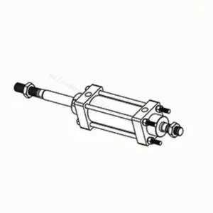
How Does A Hydraulic Control Valve Work?
A hydraulic control valve is a critical component in hydraulic systems that regulates the flow and direction of hydraulic fluid to control the operation of hydraulic actuators. It enables precise control over various hydraulic functions, such as extending or retracting cylinders, controlling motor speed and direction, or adjusting the flow rate of hydraulic fluid. Here’s an overview of how a hydraulic control valve works:
- هيكل الصمام:
- A hydraulic control valve typically consists of a valve body, spools or poppets, and various internal passages.
- The valve body contains inlet and outlet ports for fluid connection and chambers that direct the flow.
- The spools or poppets are movable elements within the valve body that control the flow paths and connect the appropriate ports.
- التحكم في التدفق:
- The hydraulic control valve regulates the flow of hydraulic fluid by opening and closing specific flow paths within the valve.
- The position of the spools or poppets determines which ports are connected and allows fluid to flow in the desired direction.
- التحكم الاتجاهي:
- Hydraulic control valves provide directional control by selectively connecting or blocking fluid flow to different hydraulic actuators.
- By adjusting the position of the spools or poppets, the valve determines which actuator receives fluid and in which direction it moves.
- Actuation Methods:
- Hydraulic control valves can be actuated using manual levers, mechanical linkages, solenoids, or pilot pressure control.
- Manual control valves are operated by moving the levers or handles to position the spools or poppets.
- Solenoid-controlled valves use electromagnetic coils to actuate the valve, allowing for remote or automated control.
- Control Modes:
- Hydraulic control valves offer different control modes, such as 2-way, 3-way, or 4-way control.
- A 2-way control valve controls flow in one direction, allowing or blocking fluid flow.
- A 3-way control valve has three ports and can control the flow between two ports while blocking the third.
- A 4-way control valve has four ports and can route fluid between two actuator ports while blocking the other two.
- Pressure Compensation:
- Some hydraulic control valves are equipped with pressure compensation features to maintain a consistent flow rate despite changes in system pressure.
- These valves adjust the flow passages based on pressure differentials, allowing for precise control regardless of varying operating conditions.
- Feedback and Control Loops:
- Advanced hydraulic control valves may incorporate feedback mechanisms, such as position or pressure sensors, to provide feedback to a control system.
- This feedback enables closed-loop control, where the system can monitor and adjust the valve’s position or flow based on desired setpoints or operating conditions.
القدرة وسعة المصنع:
(1) الجمعية
لدينا منصة تجميع بحث وتطوير مستقلة من الدرجة الأولى. تضم ورشة إنتاج الأسطوانات الهيدروليكية أربعة خطوط تجميع أسطوانات رفع شبه آلية وخط تجميع أسطوانات إمالة آلية، بطاقة إنتاجية سنوية مصممة تبلغ مليون قطعة. ورشة الأسطوانات الخاصة مجهزة بمواصفات متنوعة لنظام تجميع التنظيف شبه الآلي بطاقة إنتاجية سنوية مصممة تبلغ 200,000 قطعة، ومجهزة بمعدات تصنيع CNC الشهيرة، ومركز تصنيع، ومعدات خاصة عالية الدقة لمعالجة الأسطوانات، وآلة لحام روبوتية، وآلة تنظيف آلية، وآلة تجميع أسطوانات آلية، وخط إنتاج طلاء آلي. تضم المعدات الأساسية الحالية أكثر من 300 مجموعة (مجموعات). يضمن التوزيع الأمثل والاستخدام الفعال لموارد المعدات دقة المنتجات وتلبية احتياجات الجودة العالية.


(2) التشغيل الآلي
تم تجهيز ورشة التصنيع بمركز تحويل السكك الحديدية المائلة المخصص، ومركز التصنيع، وآلة شحذ عالية السرعة، وروبوت اللحام، وغيرها من المعدات ذات الصلة، والتي يمكنها التعامل مع معالجة أنابيب الأسطوانة بقطر داخلي أقصى يبلغ 400 مم وطول أقصى يبلغ 6 أمتار.

(3) اللحام

(4) الدهان والطلاء
مع خطوط طلاء الطلاء الأوتوماتيكية القائمة على الماء ذات الأسطوانات الصغيرة والمتوسطة الحجم، لتحقيق التحميل والتفريغ الآلي للروبوت والرش التلقائي، والقدرة التصميمية 4000 قطعة لكل وردية؛
لدينا أيضًا خط إنتاج دهانات نصف أوتوماتيكي للأسطوانات الكبيرة مدعوم بسلسلة طاقة، مع قدرة تصميمية تصل إلى 60 صندوقًا لكل وردية.


(5) الاختبار
لدينا مرافق فحص ومنصات اختبار من الدرجة الأولى لضمان أن أداء الأسطوانة يلبي المتطلبات.

نحن من أفضل مصنعي الأسطوانات الهيدروليكية. نقدم أسطوانات هيدروليكية شاملة. كما نوفر أيضًا علب التروس الزراعيةلقد صدّرن منتجاتنا إلى عملاء حول العالم، واكتسبنا سمعة طيبة بفضل جودة منتجاتنا المتميزة وخدمة ما بعد البيع المتميزة. نرحب بعملائنا المحليين والدوليين للتواصل معنا للتفاوض وتبادل المعلومات. التعاون معنا!