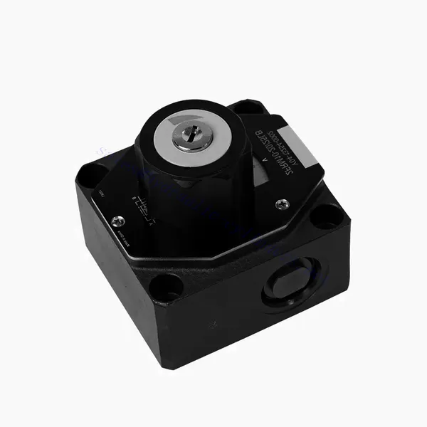
FRM Series Flow Control Hydraulic Valve
FRM Series Flow Control Hydraulic Valve
The FRM series flow control hydraulic valve is a cutting-edge hydraulic component designed to enhance the performance and control of hydraulic systems. With its advanced features and reliable functionality, this valve offers precise flow control and optimal efficiency.
The FRM series flow control hydraulic valve is a reliable and versatile solution for optimizing flow control in hydraulic systems. With its precise flow control capabilities, pressure and temperature stability, and durable construction, this valve offers enhanced performance and efficiency. Following the recommended usage methods and maintenance guidelines, operators can maximize the benefits of the FRM series flow control hydraulic valve, ensuring smooth operation and reliable flow control in their hydraulic applications. Upgrade your hydraulic system with this advanced valve and experience precision, efficiency, and productivity like never before.
FRM Series Flow Control Hydraulic Valve Key Characteristics:
- Flow Control Precision:
- The FRM series valve enables precise control over the flow rate of hydraulic fluids, allowing operators to fine-tune and regulate the speed of actuators.
- With its exceptional accuracy, this valve ensures consistent flow control, resulting in improved system performance and enhanced productivity.
- تطبيق متعدد الاستخدامات:
- The FRM series valve is highly versatile and compatible with various hydraulic systems, including industrial machinery, construction equipment, and mobile applications.
- Its adaptability makes it an ideal choice for a wide range of hydraulic setups, providing reliable and efficient flow control.
- Pressure and Temperature Stability:
- This hydraulic valve is designed to maintain consistent flow control even under varying pressure and temperature conditions.
- It ensures stable performance and prevents flow fluctuations, safeguarding the integrity and reliability of the hydraulic system.
- بناء متين:
- The FRM series valve is constructed with high-quality materials, ensuring durability and long-term reliability in demanding operating environments.
- Its robust design allows it to withstand high pressures, vibrations, and temperature extremes, providing a dependable solution for hydraulic applications.
FRM Series Flow Control Hydraulic Valve Parameter:
NG6
| Flow control valve | |||||||||||
| Max. operating pressure-Port A | حاجِز | 315 | |||||||||
| Pressure differential ΔP for free return flow B to A | See characteristic curves | ||||||||||
| Minimum pressure differential | حاجِز | 6 to 14 | |||||||||
| Pressure stability up to P= 315 bar | % | ±2(Qmax) | |||||||||
| Flow | Qmax | لتر/دقيقة | 0.2 | 0.6 | 1.5 | 3 | 6 | 10 | 16 | 25 | 32 |
| Qmin to 100bar | mL/min | 15 | 15 | 15 | 15 | 25 | 50 | 70 | 100 | 250 | |
| Qmin to 315bar | 25 | 25 | 25 | 25 | 25 | 50 | 70 | 100 | 250 | ||
| سائل | Mineral oil, Phosphate ester | ||||||||||
| نطاق درجة حرارة السائل | درجة مئوية | – 20 to + 80 | |||||||||
| نطاق اللزوجة | mm2/s | من 10 إلى 800 | |||||||||
| درجة التلوث | الحد الأقصى المسموح به لدرجة تلوث السوائل: الفئة 9. NAS 1638 أو 20/18/15، ISO4406 | ||||||||||
| موضع التثبيت | خياري | ||||||||||
| نطاق درجة الحرارة للظروف | درجة مئوية | -20 to +50 | |||||||||
| وزن | 2FRM6A…2FRM6B… | كجم | about 1.3 | ||||||||
| 2FRM6SB… | كجم | حوالي 1.5 | |||||||||
| Rectifiere | |||||||||||
| التدفق الاسمي | حاجِز | 320 | |||||||||
| أقصى ضغط تشغيل | حاجِز | to 210 | |||||||||
| ضغط الشق | حاجِز | 0.7 | |||||||||
| وزن | كجم | about 0.9 | |||||||||
NG5/10/16
| Flow control valve | ||||||||||||||||
| Max. operating pressure-Port A | حاجِز | 315 | ||||||||||||||
| Pressure differential ΔP for free return flow B to A | See characteristic curves | |||||||||||||||
| Minimum pressure differential | حاجِز | 6 to 14 | ||||||||||||||
| سائل | Mineral oil, Phosphate ester | |||||||||||||||
| نطاق درجة حرارة السائل | درجة مئوية | – 20 to + 80 | ||||||||||||||
| نطاق اللزوجة | mm2/s | من 10 إلى 800 | ||||||||||||||
| درجة التلوث | الحد الأقصى المسموح به لدرجة تلوث السوائل: الفئة 9. NAS 1638 أو 20/18/15، ISO4406 | |||||||||||||||
| مقاس | مم | 5 | 10 | 16 | ||||||||||||
| أقصى معدل تدفق | لتر/دقيقة | 0.2 | 0.6 | 1.2 | 3 | 6 | 10 | 15 | 10 | 16 | 25 | 50 | 60 | 100 | 160 | |
| Oil return flow B to A | mL/min | 0.5 | 0.5 | 0.6 | 0.9 | 1.8 | 3.6 | 6.7 | 2 | 2.5 | 3.5 | 6 | 2.8 | 4.3 | 7.3 | |
| flow stable range (%Qmax)(-20-±80℃) | ±5 | ±3 | ±2 | ±2 | ||||||||||||
| ±2 (P=210 bar) | ±2 (P=350 bar) | |||||||||||||||
| Working pressure | حاجِز | 210 | 350 | |||||||||||||
| Min.pressure drawdown | حاجِز | 3-5 | 6-8 | 3-7 | 5-12 | |||||||||||
| وزن | كجم | 1.6 | 3.4 | 7.4 | ||||||||||||
| Rectifiere | ||||||||||||||||
| سائل | Mineral oil, Phosphate ester | |||||||||||||||
| نطاق درجة حرارة السائل | من -20 إلى +80 | |||||||||||||||
| نطاق اللزوجة | من 10 إلى 800 | |||||||||||||||
| درجة التلوث | الحد الأقصى المسموح به لدرجة تلوث السوائل: الفئة 9. NAS 1638 أو 20/18/15، ISO4406 | |||||||||||||||
| مقاس | 5 | 10 | 16 | |||||||||||||
| Flow | 15 | 50 | 160 | |||||||||||||
| Working pressure | 210 | 315 | 315 | |||||||||||||
| ضغط الشق | 1 | 1.5 | 1.5 | |||||||||||||
| وزن | 0.6 | 3.2 | 9.3 | |||||||||||||
FRM Series Flow Control Hydraulic Valve Advantages:
• Base sub-plate mounting see product catalog
• Pressure compensation displacement restrictor, optional
• Optional one-directional valve
• Knob with scale, optional lockability
Usage Method Of FRM Series Flow Control Hydraulic Valve:
- تقييم النظام:
- Begin by assessing the hydraulic system’s requirements, including flow rates, pressure ranges, and desired flow control parameters.
- Determine if the FRM series valve suits the specific application based on its flow control capabilities.
- اختيار الصمام:
- Select the appropriate variant of the FRM series valve based on the system parameters, desired flow rate, and compatibility with other system components.
- Consider factors such as maximum flow capacity, pressure rating, and operational conditions.
- تثبيت:
- اتبع تعليمات التثبيت الخاصة بالشركة المصنعة بعناية، مع التأكد من المحاذاة الصحيحة وتوصيلات الصمام الآمنة.
- Pay attention to the flow direction indicators, ensuring the correct positioning of the valve in the hydraulic system.
- ضبط التحكم في التدفق:
- Once installed, adjust the flow control settings of the valve according to the desired flow rate and system requirements.
- Fine-tune the valve to achieve the desired speed and performance of hydraulic actuators, optimizing the overall system operation.
How Hydraulic Valves Work?
Hydraulic valves are crucial in controlling the flow and direction of hydraulic fluid within a hydraulic system. They are essential components that enable the precise operation of various hydraulic machinery and equipment. Here’s a simplified explanation of how hydraulic valves work:
- Basics of Hydraulic Systems:
Hydraulic systems use fluid, typically oil, to transmit power and control the movement of mechanical components. These systems consist of a hydraulic pump that pressurizes the liquid, a series of valves that control the flow and direction of the fluid, and hydraulic actuators (such as cylinders or motors) that convert the fluid energy into mechanical force or motion. - Valve Types:
There are various hydraulic valves, including directional control valves, pressure control valves, flow control valves, and check valves. Each valve type serves a specific purpose in regulating fluid flow, pressure, or direction. - صمامات التحكم الاتجاهية:
Directional control valves determine the path through which the hydraulic fluid flows. They have multiple positions (such as open, closed, or partially open) and multiple ports to direct the fluid to different sections of the hydraulic system. - Valve Components:
Hydraulic valves typically consist of a valve body, which contains internal passages and channels, and a movable valve element or spool that slides within the valve body. The spool has different lands or ports that align with the internal passages to control fluid flow. - Spool Movement:
The position of the spool within the valve body determines the flow path and, consequently, the direction of fluid flow. The spool can be actuated by various means, such as mechanical linkages, solenoids, or pilot pressure. - صمامات التحكم في الضغط:
Pressure control valves regulate the pressure of the hydraulic fluid within the system. They can maintain a specific pressure level by allowing excess fluid to return to the reservoir or blocking flow until a desired pressure is reached. - صمامات التحكم في التدفق:
Flow control valves manage the rate of fluid flow within the hydraulic system. They can be used to control the speed of hydraulic actuators or to limit the flow rate to specific sections of the system. - Check Valves:
Check valves, or one-way valves, allow fluid flow in one direction and prevent backflow. They ensure that the fluid moves in the desired direction and avoid any undesired pressure drops or loss of hydraulic force. - تشغيل الصمام:
Hydraulic valves can be manually operated, mechanically actuated, or controlled electronically. Levers or knobs directly handle manual valves, while mechanical and electronic actuators enable automated control of valve positions based on system requirements. - System Control:
By combining different types of hydraulic valves and controlling their positions or actuation, the hydraulic system’s overall function can be precisely regulated. This enables operators to control the movement, speed, force, and direction of hydraulic actuators, allowing for precise and efficient operation of hydraulic machinery.
القدرة وسعة المصنع:
(1) الجمعية
لدينا منصة تجميع بحث وتطوير مستقلة من الدرجة الأولى. تضم ورشة إنتاج الأسطوانات الهيدروليكية أربعة خطوط تجميع أسطوانات رفع شبه آلية وخط تجميع أسطوانات إمالة آلية، بطاقة إنتاجية سنوية مصممة تبلغ مليون قطعة. ورشة الأسطوانات الخاصة مجهزة بمواصفات متنوعة لنظام تجميع التنظيف شبه الآلي بطاقة إنتاجية سنوية مصممة تبلغ 200,000 قطعة، ومجهزة بمعدات تصنيع CNC الشهيرة، ومركز تصنيع، ومعدات خاصة عالية الدقة لمعالجة الأسطوانات، وآلة لحام روبوتية، وآلة تنظيف آلية، وآلة تجميع أسطوانات آلية، وخط إنتاج طلاء آلي. تضم المعدات الأساسية الحالية أكثر من 300 مجموعة (مجموعات). يضمن التوزيع الأمثل والاستخدام الفعال لموارد المعدات دقة المنتجات وتلبية احتياجات الجودة العالية.


(2) التشغيل الآلي
تم تجهيز ورشة التصنيع بمركز تحويل السكك الحديدية المائلة المخصص، ومركز التصنيع، وآلة شحذ عالية السرعة، وروبوت اللحام، وغيرها من المعدات ذات الصلة، والتي يمكنها التعامل مع معالجة أنابيب الأسطوانة بقطر داخلي أقصى يبلغ 400 مم وطول أقصى يبلغ 6 أمتار.

(3) اللحام

(4) الدهان والطلاء
مع خطوط طلاء الطلاء الأوتوماتيكية القائمة على الماء ذات الأسطوانات الصغيرة والمتوسطة الحجم، لتحقيق التحميل والتفريغ الآلي للروبوت والرش التلقائي، والقدرة التصميمية 4000 قطعة لكل وردية؛
لدينا أيضًا خط إنتاج دهانات نصف أوتوماتيكي للأسطوانات الكبيرة مدعوم بسلسلة طاقة، مع قدرة تصميمية تصل إلى 60 صندوقًا لكل وردية.


(5) الاختبار
لدينا مرافق فحص ومنصات اختبار من الدرجة الأولى لضمان أن أداء الأسطوانة يلبي المتطلبات.

نحن من أفضل مصنعي الأسطوانات الهيدروليكية. نقدم أسطوانات هيدروليكية شاملة. كما نوفر أيضًا علب التروس الزراعيةلقد صدّرن منتجاتنا إلى عملاء حول العالم، واكتسبنا سمعة طيبة بفضل جودة منتجاتنا المتميزة وخدمة ما بعد البيع المتميزة. نرحب بعملائنا المحليين والدوليين للتواصل معنا للتفاوض وتبادل المعلومات. التعاون معنا!


