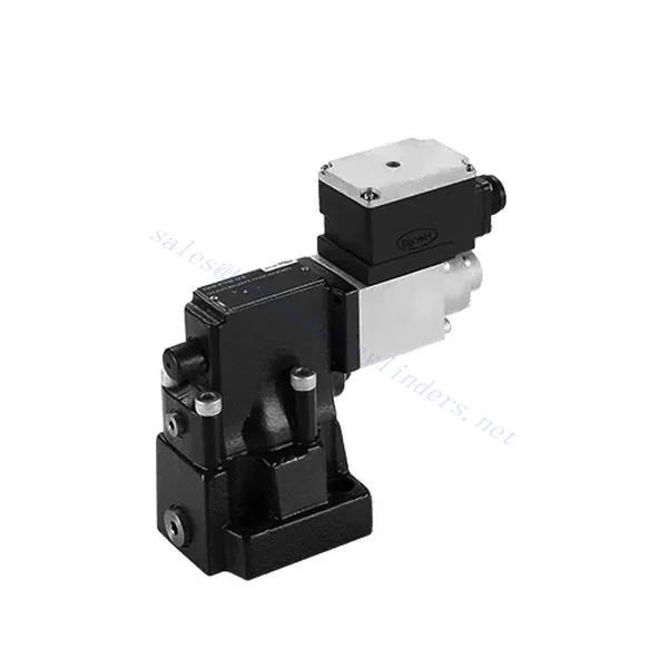
DBE/M(E) Series Proportional Pressure Relief Hydraulic Valve
DBE/M(E) Series Proportional Pressure Relief Hydraulic Valve
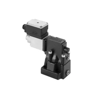
The DBE/M(E) series proportional pressure relief hydraulic valve is a state-of-the-art component designed to deliver precise pressure control in hydraulic systems. With its advanced proportional control technology, this valve ensures optimal performance, efficiency, and safety.
The DBE/M(E) series proportional pressure relief hydraulic valve empowers hydraulic systems with precise pressure control, enhanced efficiency, and equipment protection. With its advanced proportional control technology, this valve ensures optimal performance across various applications. By following the recommended usage methods and maintenance guidelines, you can maximize the benefits and reliability of the DBE/M(E) series valve, elevating the pressure control and overall performance of your hydraulic system. Upgrade your hydraulic setup today and experience superior pressure regulation with the DBE/M(E) series proportional pressure relief hydraulic valve.
DBE6X(E) Series Proportional Pressure Relief Hydraulic Valve Key Characteristics:
- تخفيف الضغط النسبي:
- The DBE/M(E) series valve offers precise and proportional pressure relief, allowing for dynamic control of hydraulic pressure.
- It ensures accurate pressure regulation in response to varying load conditions, preventing system overload and safeguarding hydraulic components.
- تحسين كفاءة النظام:
- This valve enables precise hydraulic pressure control, resulting in enhanced system efficiency and reduced energy consumption.
- By maintaining the desired pressure levels, it minimizes pressure fluctuations, optimizes system performance, and reduces operational costs.
- السلامة وحماية المعدات:
- The DBE/M(E) series valve acts as a protective mechanism by limiting the pressure within the hydraulic system, safeguarding equipment and operators.
- It prevents excessive pressure build-up, reducing the risk of component damage, system failures, and potential accidents.
- Proportional Control Functionality:
- With its proportional control technology, the DBE/M(E) series valve offers smooth and precise pressure adjustment.
- It allows for real-time pressure control, enabling seamless integration into various hydraulic systems and applications.
DBE/M(E) Series Proportional Pressure Relief Hydraulic Valve Parameter:
| عام | ||||
| سائل | زيت معدني مناسب لختم NBR و FKM | |||
| إستر الفوسفات لختم FKM | ||||
| نطاق درجة حرارة السائل | درجة مئوية | من -30 إلى +80 (أختام NBR) | ||
| من -20 إلى +80 (أختام FKM) | ||||
| نطاق اللزوجة | مم2/ث | من 2.8 إلى 380 | ||
| درجة التلوث | الحد الأقصى المسموح به لدرجة تلوث السوائل: الفئة 9. NAS 1638 أو 20/18/15، ISO4406 | |||
| أقصى ضغط تشغيل | 315 بار | |||
| المنافذ أ، ب، س | حاجِز | 50; 100; 200; 315 | ||
| أقصى ضغط ضبط | حاجِز | فيما يتعلق بالتدفق (Q)، انظر إلى المنحنيات المميزة | ||
| الحد الأدنى للضغط القابل للضبط | = الحد الأدنى للضغط القابل للضبط | |||
| الحد الأدنى للضغط القابل للضبط عند قيمة الأمر 0 | منفصل وتحت ضغط صفري للخزانات | |||
| منفذ ضغط زيت الإرجاع Y | حاجِز | ضبط الضغط | نطاق الضغط تحت أقصى ضغط أمان | |
| أقصى ضغط أمان (قابل للتعديل بلا حدود) | 50 بار | 10-60+20 حاجِز | ||
| 100 بار | 10-120+20 حاجِز | |||
| 200 بار | 10-220+20 حاجِز | |||
| 315 بار | 10-340+20 حاجِز | |||
| حالة ضبط الأمان لأقصى ضغط | When rated pressure is 50 bar, between 60 bar and 80 bar | |||
| When rated pressure is 100 bar, between120 bar and 140 bar | ||||
| When rated pressure is 200 bar, between 220 bar and 240 bar | ||||
| When rated pressure is 315 bar, between 340 bar and 360 bar | ||||
| مقاس | 10 | 25 | 32 | |
| أقصى معدل تدفق | 200 | 400 | 600 | |
| زيت التشغيل (لصمام التشغيل) | لتر/دقيقة | من 0.7 إلى 2 | ||
| الخطية | لتر/دقيقة | ±3.5% | ||
| القدرة على التكرار | <±2% | |||
| الهستيريسيس | مع اهتزاز | بدون اهتزاز | ||
| ±1.5% P max (200Hz, lapitude 200mAsss) | ±4.5% P max | |||
| وقت التبديل | 30~150ms(independent with the system) | |||
| البيانات الكهربائية | ||||
| قوة | دي سي | |||
| الحد الأدنى لتيار الملف اللولبي | مللي أمبير | 100 | ||
| أقصى تيار للملف اللولبي | مللي أمبير | 800 | ||
| مقاومة الملف | 19.5Ω at 20℃, Max. warm value: 28.8Ω | |||
| حالة العمل | مستمر | |||
| أقصى نطاق لدرجة الحرارة المحيطة | +50 درجة مئوية | |||
| التوصيل الكهربائي | موصل قابل للتوصيل وفقًا لمعيار DIN 43 650/2 +SL/PG11 | |||
| العزل وفقًا للمعيار DIN 40 050 | IP 65 | |||
| Amplifier | VT2000 | |||
DBE/M(E) Series Proportional Pressure Relief Hydraulic Valve Advantages:
• يستخدم للتركيب على اللوحة الفرعية السفلية
• يتم تركيب الواجهة وفقًا للمعيارين DIN24340 E و ISO 6264
• يستخدم في تركيب كتلة مسار الزيت
• أربعة نطاقات ضغط
• هيكل حماية من أعلى ضغط (اختياري)
• مضخم صوت إلكتروني متوافق من نوع VT-2000 (يجب طلبه بشكل منفصل)
Usage Method Of DBE/M(E) Series Proportional Pressure Relief Hydraulic Valve:
- تقييم النظام:
- Evaluate your hydraulic system and identify the specific pressure control requirements.
- Determine if the DBE/M(E) series valve is compatible with your system based on its pressure range, flow capacity, and other specifications.
- اختيار الصمام:
- Choose the appropriate DBE/M(E) series valve variant based on your system parameters, pressure range, and flow requirements.
- ضع في اعتبارك أقصى تصنيف للضغط، ووقت الاستجابة، وظروف التشغيل.
- تثبيت:
- اتبع تعليمات التثبيت الخاصة بالشركة المصنعة بعناية، مع التأكد من المحاذاة الصحيحة وتركيب الصمام بشكل آمن.
- قم بتوصيل الصمام بالنظام الهيدروليكي، مع التأكد من عدم وجود توصيلات تسرب ومحاذاة اتجاه التدفق بشكل صحيح.
- ضبط الضغط:
- Utilize the proportional control signal or adjustment mechanism provided with the DBE/M(E) series valve to set the desired pressure relief level.
- Adjust the valve incrementally, monitoring the pressure gauge readings and system response to achieve precise pressure control.
How To Adjust Hydraulic Pressure Relief Valve?
Adjusting a hydraulic pressure relief valve allows you to regulate the maximum pressure within a hydraulic system. This is important for maintaining system integrity and preventing damage to components. Here’s a step-by-step guide on how to adjust a hydraulic pressure relief valve:
- حدد صمام تخفيف الضغط:
- Locate the hydraulic pressure relief valve in your system. It is typically positioned in the hydraulic line or integrated into a manifold block.
- فهم تصميم الصمام:
- تعرّف على التصميم المحدد لصمام تخفيف الضغط الذي تعمل عليه. قد تحتوي الصمامات المختلفة على آليات ضبط مختلفة، مثل المقبض أو البرغي أو صامولة القفل.
- Determine the Desired Pressure Setting:
- Assess the requirements of your hydraulic system and determine the desired maximum pressure. Consider the system’s specifications, load conditions, and safety limits.
- إعداد النظام:
- قبل إجراء أي تعديلات، قم بإيقاف تشغيل النظام الهيدروليكي وخفف الضغط عن طريق تحريك أذرع التحكم ذهابًا وإيابًا أو باتباع الإجراء الموصى به من قبل الشركة المصنعة.
- حدد موقع آلية الضبط:
- حدد آلية الضبط الموجودة على صمام تخفيف الضغط. قد تكون مقبضًا أو برغيًا أو صامولة قفل مثبتة على جسم الصمام أو بجواره.
- اضبط الصمام:
- If the valve has a knob or handle, turn it clockwise to increase the pressure relief setting or counterclockwise to decrease it. If the valve has a screw, turn it clockwise to increase the ground or counterclockwise to drop it.
- قم بإجراء تعديلات تدريجية:
- When adjusting the pressure relief valve, make small, incremental changes to avoid sudden or drastic variations in pressure. This allows you to fine-tune the system and prevent potential damage.
- راقب النظام:
- With each adjustment, observe the hydraulic system’s pressure gauge or indicator to see the effect of the changes. Ensure that the pressure stays within the desired range.
- الاختبار والتحقق:
- Gradually increase the system’s pressure and monitor the pressure relief valve’s response. Ensure it relieves stress when the maximum set pressure is reached and maintains the desired maximum pressure.
- قم بتثبيت التعديل:
- Once you have achieved the desired pressure setting, secure the adjustment mechanism to prevent unintended changes. Some valves may have a locking nut or set screw that can be tightened to hold the adjustment in place.
- Document the Adjustment:
- Keep a record of the adjusted pressure relief setting for future reference and maintenance purposes. This documentation will help maintain consistency and aid troubleshooting efforts.
القدرة وسعة المصنع:
(1) الجمعية
لدينا منصة تجميع بحث وتطوير مستقلة من الدرجة الأولى. تضم ورشة إنتاج الأسطوانات الهيدروليكية أربعة خطوط تجميع أسطوانات رفع شبه آلية وخط تجميع أسطوانات إمالة آلية، بطاقة إنتاجية سنوية مصممة تبلغ مليون قطعة. ورشة الأسطوانات الخاصة مجهزة بمواصفات متنوعة لنظام تجميع التنظيف شبه الآلي بطاقة إنتاجية سنوية مصممة تبلغ 200,000 قطعة، ومجهزة بمعدات تصنيع CNC الشهيرة، ومركز تصنيع، ومعدات خاصة عالية الدقة لمعالجة الأسطوانات، وآلة لحام روبوتية، وآلة تنظيف آلية، وآلة تجميع أسطوانات آلية، وخط إنتاج طلاء آلي. تضم المعدات الأساسية الحالية أكثر من 300 مجموعة (مجموعات). يضمن التوزيع الأمثل والاستخدام الفعال لموارد المعدات دقة المنتجات وتلبية احتياجات الجودة العالية.


(2) التشغيل الآلي
تم تجهيز ورشة التصنيع بمركز تحويل السكك الحديدية المائلة المخصص، ومركز التصنيع، وآلة شحذ عالية السرعة، وروبوت اللحام، وغيرها من المعدات ذات الصلة، والتي يمكنها التعامل مع معالجة أنابيب الأسطوانة بقطر داخلي أقصى يبلغ 400 مم وطول أقصى يبلغ 6 أمتار.

(3) اللحام

(4) الدهان والطلاء
مع خطوط طلاء الطلاء الأوتوماتيكية القائمة على الماء ذات الأسطوانات الصغيرة والمتوسطة الحجم، لتحقيق التحميل والتفريغ الآلي للروبوت والرش التلقائي، والقدرة التصميمية 4000 قطعة لكل وردية؛
لدينا أيضًا خط إنتاج دهانات نصف أوتوماتيكي للأسطوانات الكبيرة مدعوم بسلسلة طاقة، مع قدرة تصميمية تصل إلى 60 صندوقًا لكل وردية.


(5) الاختبار
لدينا مرافق فحص ومنصات اختبار من الدرجة الأولى لضمان أن أداء الأسطوانة يلبي المتطلبات.

نحن من أفضل مصنعي الأسطوانات الهيدروليكية. نقدم أسطوانات هيدروليكية شاملة. كما نوفر أيضًا علب التروس الزراعيةلقد صدّرن منتجاتنا إلى عملاء حول العالم، واكتسبنا سمعة طيبة بفضل جودة منتجاتنا المتميزة وخدمة ما بعد البيع المتميزة. نرحب بعملائنا المحليين والدوليين للتواصل معنا للتفاوض وتبادل المعلومات. التعاون معنا!


