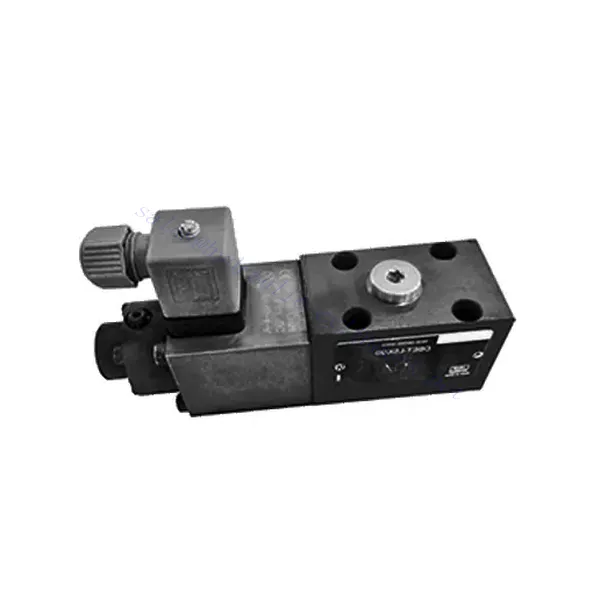
DBET(E) Series Proportional Pressure Relief Hydraulic Valve
باعتبارنا أحد مصنعي وموردي ومصدري الأسطوانات الهيدروليكية للمنتجات الميكانيكية، فإننا نقدم الأسطوانات الهيدروليكية والعديد من المنتجات الأخرى.
يرجى التواصل معنا للمزيد من التفاصيل.
بريد:sales@hydraulic-cylinders.net
الشركة المصنعة والمورد والمصدر للأسطوانات الهيدروليكية.
DBET(E) Series Proportional Pressure Relief Hydraulic Valve
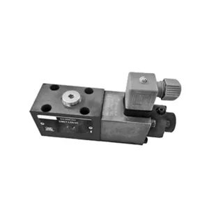
The DBET(E) series proportional pressure relief hydraulic valve is a cutting-edge component designed to deliver precise pressure control in hydraulic systems. With its advanced proportional control technology and exceptional performance, this valve optimizes system efficiency, enhances safety, and prolongs the lifespan of hydraulic equipment.
The DBET(E) series proportional pressure relief hydraulic valve is an indispensable component for achieving precise pressure control in hydraulic systems. With its proportional pressure regulation, enhanced efficiency, and equipment protection features, this valve optimizes system performance while ensuring the safety and longevity of hydraulic equipment. By following the recommended usage methods and maintenance guidelines, you can harness the full potential of the DBET(E) series proportional pressure relief hydraulic valve, maximizing the performance and reliability of your hydraulic system. Upgrade your hydraulic setup today and experience optimal pressure control with the DBET(E) series valve.
DBET(E) Series Proportional Pressure Relief Hydraulic Valve Key Characteristics:
- التحكم النسبي في الضغط:
- The DBET(E) series valve offers precise and proportional pressure relief, allowing for accurate and dynamic pressure regulation in hydraulic systems.
- It maintains a consistent pressure level against varying loads, ensuring optimal performance and preventing damage to hydraulic components.
- تحسين كفاءة النظام:
- By providing proportional pressure control, this valve helps optimize system efficiency by reducing energy consumption and minimizing pressure fluctuations.
- It ensures that hydraulic equipment operates at the desired pressure, resulting in improved productivity and reduced operational costs.
- السلامة وحماية المعدات:
- The DBET(E) Series Valve acts as a safety measure by limiting the pressure within the hydraulic system, preventing overloading and potential damage to equipment or operators.
- It safeguards sensitive components from excessive pressure, extending their lifespan and reducing the risk of system failures.
- Flexibility and Adaptability:
- This valve is available in different sizes and pressure ranges, allowing for compatibility with various hydraulic systems and applications.
- Its adaptable design makes it suitable for various industries, including manufacturing, construction, agriculture, and more.
DBET(E) Series Proportional Pressure Relief Hydraulic Valve Parameter:
| سائل | زيت معدني مناسب لختم NBR و FKM | |
| إستر الفوسفات لختم FKM | ||
| نطاق درجة حرارة السائل | درجة مئوية | من -30 إلى +80 (أختام NBR) |
| -20 to +80 (FKM seals) | ||
| نطاق اللزوجة | مم2/ث | 15 to 380 |
| درجة التلوث | Maximum permissible degree of fluid contamination: Class 9 and ISO4406 Class 20/18/15 | |
| Max. operating pressure (Port P) | حاجِز | 350 |
| أقصى ضغط ضبط | حاجِز | 50; 100; 200; 315; 350 |
| الحد الأدنى للضغط القابل للضبط | See characteristic curves | |
| الحد الأدنى للضغط القابل للضبط عند قيمة الأمر 0 | = الحد الأدنى للضغط القابل للضبط | |
| Return pressure(Port T) | حاجِز | Separate and at zero pressure to tank |
| أقصى معدل تدفق | لتر/دقيقة | 2 |
| الخطية | ± 3.5 % of max. settable pressure | |
| الهستيريسيس | ± 1.5 % of max. settable pressure | |
| القدرة على التكرار | < ± 2 % of max. settable pressure | |
| وقت التبديل | آنسة | 30 to 150 (system dependent) |
DBET(E) Series Proportional Pressure Relief Hydraulic Valve Advantages:
• مباشر، لتقييد ضغط النظام
• Installation face follows ISO 4401-03-02-0-05
• خمسة نطاقات ضغط
• Accompanying electronic amplifier VT-2000 or plugin amplifier VT-SSPA1-…-L2X (separate order)
Usage Method Of DBET(E) Series Proportional Pressure Relief Hydraulic Valve :
- تقييم النظام:
- Assess the specific requirements of your hydraulic system, including the desired pressure range, maximum flow rate, and compatibility with existing components.
- Determine if the DBET(E) series valve suits your application based on its pressure control capabilities and compatibility with your system.
- اختيار الصمام:
- Choose the appropriate variant of the DBET(E) series valve based on your system parameters, required pressure range, and flow capacity.
- ضع في اعتبارك أقصى تصنيف للضغط، ووقت الاستجابة، وظروف التشغيل.
- تثبيت:
- اتبع تعليمات التثبيت الخاصة بالشركة المصنعة بعناية، مع التأكد من المحاذاة الصحيحة وتركيب الصمام بشكل آمن.
- Connect the valve to the hydraulic system, paying attention to the flow direction indicators and ensuring leak-free connections.
- ضبط الضغط:
- Adjust the pressure relief setting of the valve to match the desired pressure range for your application.
- This can typically be achieved through proportional control signals or adjustments on the valve itself, depending on the specific model.
How To Add A Hydraulic Valve To A Tractor?
Adjusting a hydraulic flow control valve allows you to regulate the speed or flow rate of hydraulic fluid in a hydraulic system. By controlling the flow, you can optimize the performance of hydraulic cylinders, motors, or other hydraulic components. Here’s a step-by-step guide on how to adjust a hydraulic flow control valve:
- Identify the Flow Control Valve:
- Locate the flow control valve in your hydraulic system. It is typically installed in the hydraulic line leading to the component you want to control, such as a cylinder or motor.
- فهم تصميم الصمام:
- Familiarize yourself with the specific design of the flow control valve you are working with. Different valves may have varying adjustment mechanisms, such as a knob, screw, or handle.
- Determine the Desired Flow Rate:
- Assess the requirements of your hydraulic system and determine the desired flow rate or speed for the component you are controlling. This will guide you in adjusting the flow control valve accurately.
- إعداد النظام:
- قبل إجراء أي تعديلات، قم بإيقاف تشغيل النظام الهيدروليكي وخفف الضغط عن طريق تحريك أذرع التحكم ذهابًا وإيابًا أو باتباع الإجراء الموصى به من قبل الشركة المصنعة.
- حدد موقع آلية الضبط:
- Identify the adjustment mechanism on the flow control valve. It could be a knob, screw, or handle positioned on the valve body or adjacent to it.
- اضبط الصمام:
- If the valve has a knob or handle, turn it clockwise to decrease the flow rate or counterclockwise to increase the flow rate. If the valve has a screw, turn it clockwise to reduce the flow or counterclockwise to increase it.
- قم بإجراء تعديلات تدريجية:
- When adjusting the flow control valve, make small, incremental changes to avoid sudden or drastic variations in flow rate. This allows you to fine-tune the speed and achieve the desired performance.
- راقب النظام:
- With each adjustment, observe the hydraulic system and the component being controlled. Pay attention to the speed or flow rate to see if it aligns with the desired outcome.
- Test and Refine:
- Operate the hydraulic system and the controlled component to test the effectiveness of your adjustments. If necessary, continue making incremental changes until the desired flow rate or speed is achieved.
- قم بتثبيت التعديل:
- Once you have achieved the desired flow rate, secure the adjustment mechanism to prevent unintended changes. Some valves may have a locking nut or set screw that can be tightened to hold the adjustment in place.
- المراقبة وإعادة النظر:
- Regularly monitor the performance of the hydraulic system and the controlled component. If there are changes in the system or if the desired flow rate needs to be adjusted, revisit the flow control valve and repeat the adjustment process as needed.
القدرة وسعة المصنع:
(1) الجمعية
لدينا منصة تجميع بحث وتطوير مستقلة من الدرجة الأولى. تضم ورشة إنتاج الأسطوانات الهيدروليكية أربعة خطوط تجميع أسطوانات رفع شبه آلية وخط تجميع أسطوانات إمالة آلية، بطاقة إنتاجية سنوية مصممة تبلغ مليون قطعة. ورشة الأسطوانات الخاصة مجهزة بمواصفات متنوعة لنظام تجميع التنظيف شبه الآلي بطاقة إنتاجية سنوية مصممة تبلغ 200,000 قطعة، ومجهزة بمعدات تصنيع CNC الشهيرة، ومركز تصنيع، ومعدات خاصة عالية الدقة لمعالجة الأسطوانات، وآلة لحام روبوتية، وآلة تنظيف آلية، وآلة تجميع أسطوانات آلية، وخط إنتاج طلاء آلي. تضم المعدات الأساسية الحالية أكثر من 300 مجموعة (مجموعات). يضمن التوزيع الأمثل والاستخدام الفعال لموارد المعدات دقة المنتجات وتلبية احتياجات الجودة العالية.


(2) التشغيل الآلي
تم تجهيز ورشة التصنيع بمركز تحويل السكك الحديدية المائلة المخصص، ومركز التصنيع، وآلة شحذ عالية السرعة، وروبوت اللحام، وغيرها من المعدات ذات الصلة، والتي يمكنها التعامل مع معالجة أنابيب الأسطوانة بقطر داخلي أقصى يبلغ 400 مم وطول أقصى يبلغ 6 أمتار.

(3) اللحام

(4) الدهان والطلاء
مع خطوط طلاء الطلاء الأوتوماتيكية القائمة على الماء ذات الأسطوانات الصغيرة والمتوسطة الحجم، لتحقيق التحميل والتفريغ الآلي للروبوت والرش التلقائي، والقدرة التصميمية 4000 قطعة لكل وردية؛
لدينا أيضًا خط إنتاج دهانات نصف أوتوماتيكي للأسطوانات الكبيرة مدعوم بسلسلة طاقة، مع قدرة تصميمية تصل إلى 60 صندوقًا لكل وردية.


(5) الاختبار
لدينا مرافق فحص ومنصات اختبار من الدرجة الأولى لضمان أن أداء الأسطوانة يلبي المتطلبات.

نحن من أفضل مصنعي الأسطوانات الهيدروليكية. نقدم أسطوانات هيدروليكية شاملة. كما نوفر أيضًا علب التروس الزراعيةلقد صدّرن منتجاتنا إلى عملاء حول العالم، واكتسبنا سمعة طيبة بفضل جودة منتجاتنا المتميزة وخدمة ما بعد البيع المتميزة. نرحب بعملائنا المحليين والدوليين للتواصل معنا للتفاوض وتبادل المعلومات. التعاون معنا!
تطبيق الأسطوانة الهيدروليكية:
