


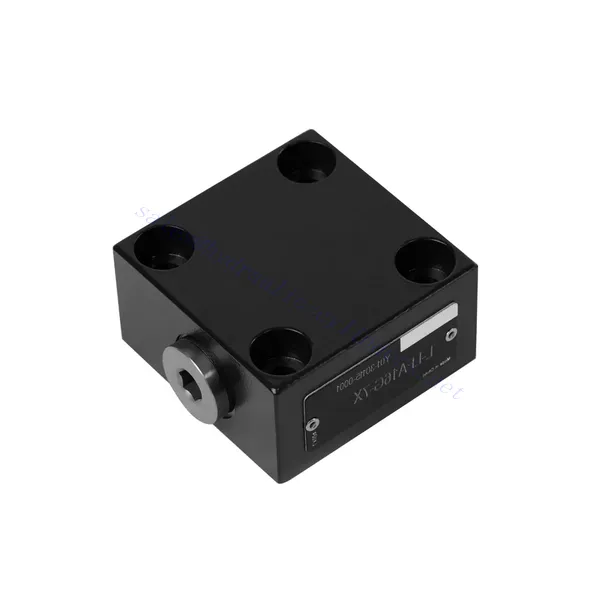
L-LFA Series Directional Control Hydraulic Valve

The L-LFA series directional control hydraulic valve is a cutting-edge component designed to deliver precise control and optimal performance in hydraulic systems. With its advanced features and robust construction, this valve provides reliable and efficient directional control for various applications.
The L-LFA series directional control hydraulic valve is a game-changer for hydraulic systems, offering precise directional control, versatility, and durability. By following the recommended usage methods and maintenance guidelines, you can harness the full potential of the L-LFA series valve and experience enhanced control, efficiency, and productivity in your hydraulic applications. Upgrade your hydraulic system today and unlock the advantages of precision and efficiency with the L-LFA series directional control hydraulic valve.
L-LFA Series Directional Control Hydraulic Valve Key Characteristics:
- Accurate Directional Control:
- The L-LFA series valve offers exceptional directional control, allowing precise and efficient management of fluid flow in hydraulic systems.
- This characteristic enables operators to direct hydraulic fluid to specific actuators or hydraulic components, facilitating smooth and controlled movement.
- Versatile Configuration Options:
- This valve is available in various configurations, including 2-way, 3-way, and 4-way options, ensuring compatibility with diverse hydraulic system requirements.
- The 2-way configuration facilitates simple on/off control, while the 3-way and 4-way configurations enable more complex functions such as cylinder extension, retraction, and bi-directional control.
- High-Performance Construction:
- The L-LFA series valve is engineered with high-quality materials and precision manufacturing techniques to ensure durability and longevity.
- Its robust construction allows it to withstand high pressures, temperature variations, and harsh operating conditions, ensuring reliable performance even in demanding environments.
- وقت الاستجابة السريع:
- This valve boasts an impressive response time, enabling rapid and efficient fluid flow control within the hydraulic system.
- The quick response time facilitates precise and immediate adjustments, resulting in enhanced system performance and reduced energy consumption.
L-LFA Series Directional Control Hydraulic Valve Parameter:
| Maximum working pressure | Without directional valve | حاجِز | 420 | |||||
| – Oil port A、B、X、Z1、Z2 | حاجِز | 315; 350; 420(Depends on top-mounted directional valve) | ||||||
| – Oil port Y | حاجِز | Equivalent to the return pressure of a top-mounted directional valve | ||||||
| سائل | زيت معدني مناسب لختم NBR و FKM | |||||||
| إستر الفوسفات لختم FKM | ||||||||
| نطاق درجة حرارة السائل | درجة مئوية | -30 إلى +80 (ختم NBR) | ||||||
| -20 إلى +80 (ختم FKM) | ||||||||
| نطاق اللزوجة | مم2/ث | 2.8 to 380 | ||||||
| درجة التلوث | الحد الأقصى المسموح به لدرجة تلوث السوائل: الفئة 9. NAS 1638 أو 20/18/15، ISO4406 | |||||||
L-LFA Series Directional Control Hydraulic Valve Advantages:
• Basic type D with remote control
• With stroke limiter H
• Built-in shuttle valve G
• Built-in directional seat valve R, RF
• Can be equipped with directional valve WE
Usage Method Of L-LFA Series Directional Control Hydraulic Valve:
- تقييم النظام:
- Evaluate your hydraulic system and identify the specific directional control requirements.
- Determine whether the L-LFA series valve suits your system based on flow rates, pressure ratings, and compatibility with your application.
- اختيار الصمام:
- Select the appropriate variant of the L-LFA series valve based on your system parameters and directional control needs.
- Consider factors such as valve type (2-way, 3-way, or 4-way), flow capacity, pressure rating, and compatibility with your specific application.
- تثبيت:
- Follow the manufacturer’s installation instructions carefully to ensure proper alignment and secure valve mounting.
- Use compatible hydraulic fittings, adapters, and seals to establish leak-free connections. Tighten the connections adequately, avoiding overtightening that could damage the valve or fittings.
- تكامل النظام:
- Connect the hydraulic lines to the appropriate ports of the L-LFA series valve, ensuring the correct flow direction.
- Verify that the valve is installed in the correct orientation, as indicated by the directional arrows on the valve body.
- التشغيل والتحكم:
- Familiarize yourself with the control mechanisms of the L-LFA Series Valve, such as levers, knobs, or solenoids.
- Ensure that the valve is actuated correctly and that the desired hydraulic flow is achieved based on the system requirements.
كيفية تركيب صمام تخفيف الضغط الهيدروليكي؟
Installing a hydraulic pressure relief valve is a crucial step in ensuring the safety and proper functioning of a hydraulic system. Here’s a step-by-step guide on how to install a hydraulic pressure relief valve:
- تحديد الصمام: حدد نوع وطراز صمام تخفيف الضغط الهيدروليكي الذي تستخدمه. تأكد من ملاءمته لتطبيقك وتوافقه مع متطلبات نظامك الهيدروليكي.
- جمع الأدوات والمواد المطلوبة: Collect the necessary tools and materials, including appropriate hydraulic fittings, adapters, wrenches, Teflon tape (thread sealant), and a pressure gauge if needed. Refer to the manufacturer’s instructions for any specific tools or components required.
- تحضير النظام الهيدروليكي: أوقف تشغيل النظام الهيدروليكي وخفّض الضغط بتفعيل صمام تخفيف الضغط أو سحب الأسطوانات الهيدروليكية. هذه الخطوة بالغة الأهمية للسلامة، وتمنع أي حركة عرضية أو تسرب للسائل الهيدروليكي.
- تحديد نقطة تخفيف الضغط: حدد الموقع الأمثل لتركيب صمام تخفيف الضغط الهيدروليكي في نظامك الهيدروليكي. يجب وضعه أسفل المضخة، قبل أي مكونات حساسة لحمايتها من الضغط الزائد. راجع مخطط النظام الهيدروليكي أو استشر متخصصًا إذا لزم الأمر.
- تركيب الصمام: Securely mount the hydraulic pressure relief valve in the chosen location using appropriate brackets or clamps. Ensure the valve is positioned correctly, aligning the inlet and outlet ports with the flow direction. Follow the manufacturer’s instructions for specific mounting requirements.
- قم بتوصيل منافذ الإدخال والإخراج: ثبت الخراطيم أو الأنابيب الهيدروليكية بمنافذ دخول وخروج صمام تخفيف الضغط. استخدم وصلات ومحولات هيدروليكية مناسبة لضمان توصيل آمن. ضع شريط تفلون أو مانع تسرب على الخيوط الذكرية للوصلات لضمان توصيل محكم ومحكم. أحكم ربط الوصلات باستخدام مفاتيح لتجنب التسرب، مع الحرص على عدم الإفراط في الربط.
- ضبط إعداد تخفيف الضغط: Most hydraulic pressure relief valves come with an adjustable pressure relief setting. Adjust the relief valve to the desired pressure relief point using the manufacturer’s guidelines. Some valves may require a pressure gauge to accurately set the relief pressure. Install the pressure gauge temporarily, if needed, and adjust the relief valve until the desired pressure is achieved.
- اختبار النظام: بعد تركيب صمام تخفيف الضغط الهيدروليكي، استعد ضغط النظام الهيدروليكي تدريجيًا. راقب مقياس الضغط أو راقب أداء النظام للتأكد من عمل صمام تخفيف الضغط بشكل صحيح. يجب أن ينفتح صمام تخفيف الضغط ويصرف الضغط الزائد عند وصوله إلى نقطة الضبط، مما يمنع تلف النظام.
- مراقبة وصيانة: Regularly inspect the hydraulic pressure relief valve for any signs of leakage, damage, or reduced performance. Clean the valve and surrounding area to remove dirt and debris that may affect its operation. Follow the manufacturer’s recommended maintenance schedule and guidelines to ensure optimal performance and longevity.
القدرة وسعة المصنع:
(1) الجمعية
لدينا منصة تجميع بحث وتطوير مستقلة من الدرجة الأولى. تضم ورشة إنتاج الأسطوانات الهيدروليكية أربعة خطوط تجميع أسطوانات رفع شبه آلية وخط تجميع أسطوانات إمالة آلية، بطاقة إنتاجية سنوية مصممة تبلغ مليون قطعة. ورشة الأسطوانات الخاصة مجهزة بمواصفات متنوعة لنظام تجميع التنظيف شبه الآلي بطاقة إنتاجية سنوية مصممة تبلغ 200,000 قطعة، ومجهزة بمعدات تصنيع CNC الشهيرة، ومركز تصنيع، ومعدات خاصة عالية الدقة لمعالجة الأسطوانات، وآلة لحام روبوتية، وآلة تنظيف آلية، وآلة تجميع أسطوانات آلية، وخط إنتاج طلاء آلي. تضم المعدات الأساسية الحالية أكثر من 300 مجموعة (مجموعات). يضمن التوزيع الأمثل والاستخدام الفعال لموارد المعدات دقة المنتجات وتلبية احتياجات الجودة العالية.


(2) التشغيل الآلي
تم تجهيز ورشة التصنيع بمركز تحويل السكك الحديدية المائلة المخصص، ومركز التصنيع، وآلة شحذ عالية السرعة، وروبوت اللحام، وغيرها من المعدات ذات الصلة، والتي يمكنها التعامل مع معالجة أنابيب الأسطوانة بقطر داخلي أقصى يبلغ 400 مم وطول أقصى يبلغ 6 أمتار.


(3) اللحام


(4) الدهان والطلاء
مع خطوط طلاء الطلاء الأوتوماتيكية القائمة على الماء ذات الأسطوانات الصغيرة والمتوسطة الحجم، لتحقيق التحميل والتفريغ الآلي للروبوت والرش التلقائي، والقدرة التصميمية 4000 قطعة لكل وردية؛
لدينا أيضًا خط إنتاج دهانات نصف أوتوماتيكي للأسطوانات الكبيرة مدعوم بسلسلة طاقة، مع قدرة تصميمية تصل إلى 60 صندوقًا لكل وردية.


(5) الاختبار
لدينا مرافق فحص ومنصات اختبار من الدرجة الأولى لضمان أن أداء الأسطوانة يلبي المتطلبات.


نحن من أفضل مصنعي الأسطوانات الهيدروليكية. نقدم أسطوانات هيدروليكية شاملة. كما نوفر أيضًا علب التروس الزراعيةلقد صدّرن منتجاتنا إلى عملاء حول العالم، واكتسبنا سمعة طيبة بفضل جودة منتجاتنا المتميزة وخدمة ما بعد البيع المتميزة. نرحب بعملائنا المحليين والدوليين للتواصل معنا للتفاوض وتبادل المعلومات. التعاون معنا!