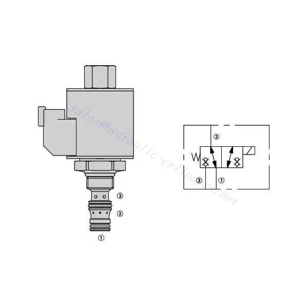
30SD38-38 Електромагнитен насочващ вентил
Като един от производителите, доставчиците и износителите на хидравлични цилиндри, ние предлагаме хидравлични цилиндри и много други продукти.
Моля, свържете се с нас за подробности.
Поща:sales@hydraulic-cylinders.net
Производител, доставчик и износител на хидравлични цилиндри.
30SD38-38 Електромагнитен насочващ вентил
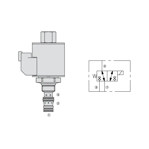
The 30SD38-38 solenoid directional valve is a highly efficient and versatile component that plays a pivotal role in fluid control systems. This valve is designed to deliver precise and reliable fluid control and offers exceptional performance and durability.
The 30SD38-38 solenoid directional valve is a reliable and efficient fluid control solution for various industrial applications. With its robust construction, efficient performance, and versatile mounting options, this valve provides precise control over fluid flow and enhances overall system performance. By following proper usage methods and implementing regular maintenance practices, you can ensure optimal functionality and longevity of the 30SD38-38 solenoid directional valve, making it an excellent choice for your fluid control needs.
30SD38-38 Solenoid Directional Valve Characteristics:
- Robust Construction: The 30SD38-38 solenoid directional valve is constructed with high-quality materials, ensuring durability and resistance to wear and corrosion. Its rugged design allows it to withstand harsh operating conditions, making it suitable for various industrial applications.
- Efficient Performance: Powered by a solenoid, this valve provides rapid response times, enabling quick adjustments to fluid flow and pressure. The efficient operation ensures precise control and seamless integration into automated processes.
- Versatile Mounting Options: The valve offers flexible mounting options, including inline, manifold, or subplate configuration. This versatility allows for easy installation and integration into various fluid control systems, accommodating different application requirements.
30SD38-38 Solenoid Directional Valve Parameter:
| Номинално налягане | 207 бара (3000 psi) | |
| Пиков поток | Вижте диаграмата на производителността | |
| Вътрешен теч | ≤5 drops/min@207bar | |
| Номинална товароносимост на бобината | Непрекъснато от 85% до 115% на номинално напрежение | |
| Начална консумация на ток на бобината при 20℃ | Електронна бобина | 1.7A при 12VDC; 0.85A при 24VDC |
| D-бобина | 1,67 A при 12 VDC; 0,83 A при 24 VDC | |
| Минимално напрежение на включване | 85% с номинално налягане 207 бара (3000 psi) | |
| Кухина | VC08-3 | |
| Течност | Минерални или синтетични масла със смазочни свойства | |
| Диапазон на температурата на флуида ℃ | -54 до 107 ℃ (полиуретанови уплътнения) | |
| -40 до 100 ℃ (уплътнения Buna N) | ||
| -26 до 204 ℃ (флуоровъглеродни уплътнения) | ||
| Диапазон на вискозитет | 7,4 до 420 мм2/с | |
| Степен на замърсяване | Минималното ниво на замърсяване е ISO4406 ниво 20/18/14, а ниво 17/15/13 се препоръчва за удължаване на експлоатационния живот. | |
30SD38-38 Solenoid Directional Valve Advantages:
• Бобина с номинален капацитет за непрекъсната работа
• Патроните са взаимозаменяеми по напрежение
• Опционални водоустойчиви електрически бобини със степен на защита до IP69K
• Ефективна конструкция с мокра арматура
• Обща кухина в индустрията
• Закалени части за дълъг живот
Usage Method Of 30SD38-38 Solenoid Directional Valve:
- Determine the application requirements: Identify the specific fluid control needs of your system. Consider factors such as flow rate, pressure, and direction to select the appropriate valve configuration.
- Mount the valve: Choose the suitable mounting option based on your system’s layout and available space. Ensure that the valve is securely positioned and aligned with the fluid lines.
- Connect the fluid lines: Use compatible fittings and connectors to establish the necessary connections between the valve and the fluid lines. Ensure tight and leak-free connections.
- Electrical connection: Connect the solenoid valve to the appropriate power source following the manufacturer’s instructions. Ensure proper wiring and observe safety precautions.
- Test and adjust: Once the valve is installed and connected, gradually introduce fluid flow and monitor its behavior. Test different operating conditions and adjust the valve settings as needed to achieve the desired fluid control.
How To Replace A Shower Mixing Valve Cartridge?
Replacing a shower mixing valve cartridge is a common DIY task that can help restore proper water temperature and flow control. Here’s a step-by-step guide on how to replace a shower mixing valve cartridge:
- Gather the necessary tools: Before starting the replacement process, gather the following tools: adjustable wrench, Phillips screwdriver, flathead screwdriver, pliers, Allen wrench (if applicable), and a replacement cartridge specific to your shower valve model.
- Turn off the water supply: Locate the main water shut-off valve for your home and turn it off to stop the water flow to the shower. If there isn’t a dedicated shut-off valve for the shower, you may need to shut off the main water supply.
- Remove the handle and trim: Start by removing the handle. Depending on the type of handle, you may need to locate a set screw or a decorative cap covering the screw. Use a flathead or Phillips screwdriver to remove the screw or pry off the cap, allowing you to detach the handle. Next, remove any trim or decorative coverings around the valve by gently pulling or unscrewing them.
- Access the cartridge: Depending on the valve design, you may need to remove additional components to access the cartridge. This can include a retaining nut, sleeve, or escutcheon plate. Use the appropriate tools to remove these components and expose the cartridge.
- Remove the old cartridge: Once you have clear access to the cartridge, use pliers or a specialized cartridge removal tool, if provided, to carefully pull out the old cartridge. Wiggle it back and forth if necessary. Be cautious not to damage any surrounding plumbing connections.
- Clean the valve body: Before installing the new cartridge, clean the valve body thoroughly to remove any debris or mineral buildup. Wipe it with a clean cloth or use a mild cleaning solution if needed.
- Install the new cartridge: Take the replacement cartridge and align it with the valve body, ensuring that any tabs or notches match up correctly. Push the cartridge firmly into place until it sits flush with the valve body.
- Reassemble the valve: Put back any components you removed earlier, such as the retaining nut, sleeve, or escutcheon plate. Make sure they are tightened securely but avoid overtightening.
- Test for leaks: Turn on the water supply and carefully observe the valve for any leaks. If you notice any leaks, tighten the connections or adjust the cartridge as needed. Check both the hot and cold water settings to ensure proper temperature control.
- Reinstall the trim and handle: Once you’ve confirmed that there are no leaks, reinstall the trim or decorative coverings over the valve. Slide the handle back onto the cartridge stem and secure it with the set screw or by replacing the decorative cap.
- Restore water supply: Finally, turn on the main water supply or the dedicated shut-off valve for the shower and test the functionality of the new cartridge. Verify that the water temperature and flow can be adjusted smoothly.
Възможности и капацитет на фабриката:
(1) Сглобяване
Разполагаме с първокласна независима платформа за научноизследователска и развойна дейност. Цехът за производство на хидравлични цилиндри разполага с четири полуавтоматични линии за монтаж на повдигащи цилиндри и една автоматична линия за монтаж на накланящи се цилиндри, с проектиран годишен производствен капацитет от 1 милион броя. Цехът за специални цилиндри е оборудван с различни спецификации на полуавтоматична система за почистване и монтаж с проектиран годишен производствен капацитет от 200 000 броя и е оборудван с известно CNC машинно оборудване, обработващ център, специално оборудване за високопрецизна обработка на цилиндри, роботизирана заваръчна машина, автоматична машина за почистване, автоматична машина за монтаж на цилиндри и автоматична производствена линия за боядисване. Съществуващото критично оборудване е повече от 300 комплекта. Оптималното разпределение и ефективното използване на ресурсите на оборудването гарантират изискванията за точност на продуктите и отговарят на висококачествените нужди на продуктите.


(2) Машинна обработка
Машинният цех е оборудван със специализиран струговащ център за наклонени релси, обработващ център, високоскоростна хонингова машина, заваръчен робот и друго свързано оборудване, което може да обработва цилиндрични тръби с максимален вътрешен диаметър 400 мм и максимална дължина 6 метра.

(3) Заваряване

(4) Боядисване и покритие
С малки и средни цилиндрични автоматични линии за боядисване на водна основа, за постигане на автоматично роботизирано товарене и разтоварване и автоматично пръскане, проектният капацитет е 4000 броя на смяна;
Разполагаме и с полуавтоматична линия за производство на бои за големи цилиндри, задвижвана от силова верига, с проектен капацитет от 60 каси на смяна.


(5) Тестване
Разполагаме с първокласни инспекционни съоръжения и тестови стендове, за да гарантираме, че производителността на цилиндъра отговаря на изискванията.

Ние сме едни от най-добрите производители на хидравлични цилиндри. Можем да предложим цялостни хидравлични цилиндри. Предлагаме и съответните... селскостопански скоростни кутииИзнасяме продуктите си за клиенти по целия свят и сме си спечелили добра репутация благодарение на превъзходното качество на продуктите и следпродажбеното обслужване. Приветстваме клиенти от страната и чужбина да се свържат с нас, за да преговарят за бизнес, да обменят информация и... сътрудничете с нас!
Приложение на хидравличния цилиндър:
