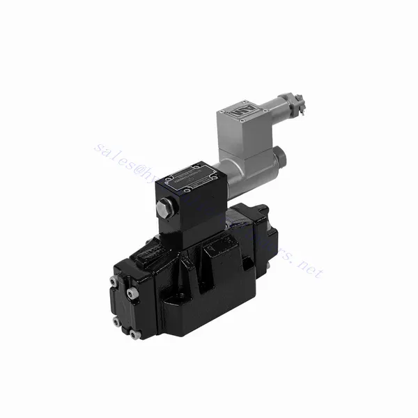
Взривозащитен насочен хидравличен вентил серия GWEH
Като един от производителите, доставчиците и износителите на хидравлични цилиндри, ние предлагаме хидравлични цилиндри и много други продукти.
Моля, свържете се с нас за подробности.
Поща:sales@hydraulic-cylinders.net
Производител, доставчик и износител на хидравлични цилиндри.
Взривозащитен насочен хидравличен вентил серия GWEH
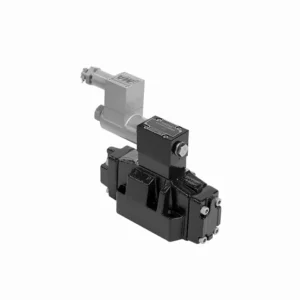
The GWEH series explosion-proof directional hydraulic valve is an innovative solution designed to provide optimal safety and precise control in hydraulic systems operating in hazardous environments. With its explosion-proof features, reliable performance, and advanced functionalities, this valve offers enhanced safety measures, efficient fluid flow control, and compatibility with various industrial applications.
The GWEH series explosion-proof directional hydraulic valve is a reliable and efficient solution for industries operating in hazardous environments. With its explosion-proof design, precise directional control, versatility, and high performance, this valve ensures safety and control in hydraulic systems. Following the recommended usage methods and adhering to regular maintenance practices, the GWEH series valve delivers safe and efficient operation in explosive atmospheres. Upgrade your hydraulic system with the GWEH series explosion-proof directional hydraulic valve and experience enhanced safety, optimal fluid flow control, and reliable performance.
GWEH Series Explosion-proof Directional Hydraulic Valve Key Characteristics:
- Explosion-proof Design:
- The GWEH series valve is engineered with a robust explosion-proof design, ensuring safe operation in environments containing flammable gases or dust.
- It complies with stringent safety standards and certifications, minimizing the risk of ignition and ensuring the safety of personnel and equipment.
- Контрол на посоката:
- This hydraulic valve provides precise directional control of fluid flow, allowing for the activation and deactivation of specific hydraulic actuators.
- It enables smooth and reliable operation of various hydraulic functions, such as cylinder extension and retraction or motor direction changes.
- Универсалност и съвместимост:
- The GWEH series valve is highly versatile and compatible with various hydraulic systems and applications.
- It can seamlessly integrate into industrial machinery, mobile equipment, and automation systems operating in hazardous environments.
- Висока производителност:
- With its advanced design and high-quality construction, the GWEH series hydraulic valve delivers exceptional performance and reliability.
- It ensures consistent and precise control over fluid flow, contributing to efficient and optimized system operation.
GWEH Series Explosion-proof Directional Hydraulic Valve Parameter:
НГ10
| Working pressureP,A,B | бар | 315 | |||||||||
| Порт Т | With external pilot oil drain | бар | 315 | ||||||||
| With internal pilot oil drain | бар | 210 | |||||||||
| Порт Y | With external pilot oil drain | бар | 210 | ||||||||
| Мин. контролно налягане | С външно захранване с пилотно масло
С вътрешно захранване с пилотно масло (not apply to C, Z, F, G, H, P, T, V) |
бар | 3-position valve 10 | ||||||||
| Spring-return 2-position valve 10 | |||||||||||
| Hydraulic-return 2-position valve 7 | |||||||||||
| С вътрешно захранване с пилотно масло ( apply to C, Z, F, G, H, P, T, V) |
бар | 4.5 | |||||||||
| Max. control pressure | бар | 250 | |||||||||
| Течност | Минерално масло, фосфатен естер | ||||||||||
| Диапазон на температурата на флуида | ℃ | -30 до +80 (уплътнения от NBR) | |||||||||
| -20 до +80 (уплътнения от FKM) | |||||||||||
| Диапазон на вискозитет | мм2/с | 2,8 до 500 | |||||||||
| Controlled quantity in commutating process | cm3 | 3-position valve 2.04 2-position valve 4.08 | |||||||||
| Switching times (= Valve switching time from the neutral position to the switched position)(DC ) | |||||||||||
| Control pressure | бар | 70 | 140 | 210 | 250 | ||||||
| 3-position valve | мс | 65 | 60 | 55 | 50 | ||||||
| 2-position valve | мс | 80 | 75 | 70 | 65 | ||||||
| Времена за превключване (= Време за превключване на вентила от включено положение в неутрално положение) | |||||||||||
| 3-position valve | мс | 30 | |||||||||
| 2-position valve | мс | 35 | 40 | 30 | 35 | 25 | 30 | 20 | 25 | ||
| Flow of shortest switching time | л/мин | около 35 | |||||||||
| Позиция на монтажа | HC, HD, HK, HZ and HY of hydraulic return shall be installed horizontally. The rest are arbitrary | ||||||||||
НГ16
| Спецификации | G-..WEH16../6B2.. type | |||||||
| Working pressureP,A,B bar | 350 | |||||||
| Порт Т | С външна дренажна шина за пилотно масло | 250 | ||||||
| С вътрешна дренажна шина за пилотно масло | 210 | |||||||
| Hydraulic-centering 3-position valve With internal pilot oil drain is impossible | ||||||||
| Порт Y | С външна дренажна шина за пилотно масло | 210 | ||||||
| Мин. контролно налягане | With external pilot oil supply bar
With internal pilot oil supply bar |
3-position valve 14 | ||||||
| Двупозиционен вентил с пружинно връщане 14 | ||||||||
| Hydraulic-return 2-position valve 14 | ||||||||
| С вътрешно захранване с пилотно масло ( apply to C、Z、F、G、H、P、T、V) bar |
When applying back pressure valve or the flow is large, enginery of spool valve is 4.5 bar as C、Z、F、G、H、P、T and V | |||||||
| Максимално управляващо налягане bar | 250 | |||||||
| Течност | Минерално масло, фосфатен естер | |||||||
| Диапазон на температурата на флуида ℃ | -30 до +80 (уплътнения от NBR) | |||||||
| -20 до +80 (уплътнения от FKM) | ||||||||
| Viscosity range mm2 /s 2 | 2,8 до 500 | |||||||
| Превключване на обема на пилотното масло | ||||||||
| -Spring-centering 3-position valve cm3 | 5.72 | |||||||
| -2-position valve cm3 | 11.45 | |||||||
| * Времена за превключване (= Време за превключване на вентила от неутрално положение в превключено положение) (AC и DC) | ||||||||
| Контролно налягане бар | 50 | 150 | 250 | |||||
| – Spring-centering 3-position valve ms | 65 | 60 | 58 | |||||
| – 2-position valve ms | 65 | 55 | 50 | |||||
| *Времена превключване (= Време за превключване на вентила от неутрално положение в положение на превключване) | ||||||||
| – Spring-centering 3-position valve ms | 40 | |||||||
| – 2-position valve ms | 45 | 35 | 30 | |||||
| Позиция на монтажа | C,D,K,Z,Y Type hydraulic-return valves are installed horizontally, the rest can be installed arbitrarily。 | |||||||
| Flow of shorter switching time L/min | около 35 | |||||||
| Weight of the valve kg | about 10.6 | |||||||
НГ25
| Спецификации | G-H-…WEH25../6B2… type | |||||||||
| Working pressureP,A,B bar | 350 | |||||||||
| Порт Т | С външна дренажна шина за пилотно масло | 250 | ||||||||
| С вътрешна дренажна шина за пилотно масло | 210 | |||||||||
| Hydraulic-centering 3-position valve With internal pilot oil drain is impossible | ||||||||||
| Порт Y | С външна дренажна шина за пилотно масло | 210 | ||||||||
| Мин. контролно налягане | With external pilot oil supply bar
With internal pilot oil supply bar |
Spring-centering 3-position valve 13 | ||||||||
| Hydraulic-centering 3-position valve 18 | ||||||||||
| Spring-return 2-position valve 13 | ||||||||||
| Hydraulic-return 2-position valve 18 | ||||||||||
| С вътрешно захранване с пилотно масло | When applying back pressure valve or the flow is large, enginery of spool valve is 4.5 bar as C、Z、F、G、H、P、T and V | |||||||||
| Максимално управляващо налягане bar | 250 | |||||||||
| Течност | Минерално масло, фосфатен естер | |||||||||
| Диапазон на температурата на флуида ℃ | -30 до +80 (уплътнения от NBR) | |||||||||
| -20 до +80 (уплътнения от FKM) | ||||||||||
| Viscosity range mm2 /s 2 | 2,8 до 500 | |||||||||
| Превключване на обема на пилотното масло | ||||||||||
| -Spring-centering 3-position valve cm3 | 14.2 | |||||||||
| -2-position valve cm3 | 28.4 | |||||||||
| * Времена за превключване (= Време за превключване на вентила от неутрално положение в превключено положение) (AC и DC) | ||||||||||
| Контролно налягане бар | 50 | 140 | 210 | 250 | ||||||
| – Spring-centering 3-position valve ms | 85 | 75 | 70 | 65 | ||||||
| – 2-position valve ms | 160 | 130 | 120 | 105 | ||||||
| **Времена превключване (= Време за превключване на вентила от неутрално положение в положение на превключване) | ||||||||||
| – Spring-centering 3-position valve ms | 40 | |||||||||
| – 2-position valve ms | 125 | 100 | 90 | 80 | ||||||
| Позиция на монтажа | C,D,K,Z,Y Type hydraulic-return valves are installed horizontally, the rest can be installed arbitrarily。 | |||||||||
| Flow of shorter switching time L/min | около 35 | |||||||||
| Weight of the valve kg | about 19 | |||||||||
GWEH Series Explosion-proof Directional Hydraulic Valve Advantages:
• Directional valve directional the oil path by controlling the main spool
• WEH електрохидравлично управление
• Two-position four-way or three-position four-way
• Installation face follows DIN 24340 A, ISO 4401, and CETOP-RP 121H Sub-plate mounting connection
• Сменете бобината без изпускане на масло
Usage Method Of GWEH Series Explosion-proof Directional Hydraulic Valve :
- Hazardous Area Assessment:
- Conduct a thorough assessment of the hazardous area to identify the specific explosion-proof requirements and classification.
- Determine the appropriate safety measures and precautions needed to comply with the regulations.
- Избор на клапан:
- Select the GWEH Series Valve with the suitable specifications, considering factors such as pressure ratings, flow capacity, and voltage requirements.
- Ensure compatibility with the hydraulic system and the specific hazardous environment.
- Монтаж:
- Follow the manufacturer’s instructions for proper installation of the GWEH Series Valve in the hydraulic system.
- Ensure secure mounting and proper electrical connections, adhering to the recommended torque values and wiring guidelines.
- Control and Activation:
- Utilize the recommended control method, such as electrical signals or remote activation, to operate the GWEH Series Valve.
- Connect the valve to a suitable power source and control system, following the provided wiring diagrams.
How Does A Hydraulic Control Valve Work?
A hydraulic control valve is a critical component in hydraulic systems that regulates the flow and direction of hydraulic fluid to control the operation of hydraulic actuators. It enables precise control over various hydraulic functions, such as extending or retracting cylinders, controlling motor speed and direction, or adjusting the flow rate of hydraulic fluid. Here’s an overview of how a hydraulic control valve works:
- Структура на клапана:
- A hydraulic control valve typically consists of a valve body, spools or poppets, and various internal passages.
- The valve body contains inlet and outlet ports for fluid connection and chambers that direct the flow.
- The spools or poppets are movable elements within the valve body that control the flow paths and connect the appropriate ports.
- Контрол на потока:
- The hydraulic control valve regulates the flow of hydraulic fluid by opening and closing specific flow paths within the valve.
- The position of the spools or poppets determines which ports are connected and allows fluid to flow in the desired direction.
- Контрол на посоката:
- Hydraulic control valves provide directional control by selectively connecting or blocking fluid flow to different hydraulic actuators.
- By adjusting the position of the spools or poppets, the valve determines which actuator receives fluid and in which direction it moves.
- Actuation Methods:
- Hydraulic control valves can be actuated using manual levers, mechanical linkages, solenoids, or pilot pressure control.
- Manual control valves are operated by moving the levers or handles to position the spools or poppets.
- Solenoid-controlled valves use electromagnetic coils to actuate the valve, allowing for remote or automated control.
- Control Modes:
- Hydraulic control valves offer different control modes, such as 2-way, 3-way, or 4-way control.
- A 2-way control valve controls flow in one direction, allowing or blocking fluid flow.
- A 3-way control valve has three ports and can control the flow between two ports while blocking the third.
- A 4-way control valve has four ports and can route fluid between two actuator ports while blocking the other two.
- Компенсация на налягането:
- Some hydraulic control valves are equipped with pressure compensation features to maintain a consistent flow rate despite changes in system pressure.
- These valves adjust the flow passages based on pressure differentials, allowing for precise control regardless of varying operating conditions.
- Feedback and Control Loops:
- Advanced hydraulic control valves may incorporate feedback mechanisms, such as position or pressure sensors, to provide feedback to a control system.
- This feedback enables closed-loop control, where the system can monitor and adjust the valve’s position or flow based on desired setpoints or operating conditions.
Възможности и капацитет на фабриката:
(1) Сглобяване
Разполагаме с първокласна независима платформа за научноизследователска и развойна дейност. Цехът за производство на хидравлични цилиндри разполага с четири полуавтоматични линии за монтаж на повдигащи цилиндри и една автоматична линия за монтаж на накланящи се цилиндри, с проектиран годишен производствен капацитет от 1 милион броя. Цехът за специални цилиндри е оборудван с различни спецификации на полуавтоматична система за почистване и монтаж с проектиран годишен производствен капацитет от 200 000 броя и е оборудван с известно CNC машинно оборудване, обработващ център, специално оборудване за високопрецизна обработка на цилиндри, роботизирана заваръчна машина, автоматична машина за почистване, автоматична машина за монтаж на цилиндри и автоматична производствена линия за боядисване. Съществуващото критично оборудване е повече от 300 комплекта. Оптималното разпределение и ефективното използване на ресурсите на оборудването гарантират изискванията за точност на продуктите и отговарят на висококачествените нужди на продуктите.


(2) Машинна обработка
Машинният цех е оборудван със специализиран струговащ център за наклонени релси, обработващ център, високоскоростна хонингова машина, заваръчен робот и друго свързано оборудване, което може да обработва цилиндрични тръби с максимален вътрешен диаметър 400 мм и максимална дължина 6 метра.

(3) Заваряване

(4) Боядисване и покритие
С малки и средни цилиндрични автоматични линии за боядисване на водна основа, за постигане на автоматично роботизирано товарене и разтоварване и автоматично пръскане, проектният капацитет е 4000 броя на смяна;
Разполагаме и с полуавтоматична линия за производство на бои за големи цилиндри, задвижвана от силова верига, с проектен капацитет от 60 каси на смяна.


(5) Тестване
Разполагаме с първокласни инспекционни съоръжения и тестови стендове, за да гарантираме, че производителността на цилиндъра отговаря на изискванията.

Ние сме едни от най-добрите производители на хидравлични цилиндри. Можем да предложим цялостни хидравлични цилиндри. Предлагаме и съответните... селскостопански скоростни кутииИзнасяме продуктите си за клиенти по целия свят и сме си спечелили добра репутация благодарение на превъзходното качество на продуктите и следпродажбеното обслужване. Приветстваме клиенти от страната и чужбина да се свържат с нас, за да преговарят за бизнес, да обменят информация и... сътрудничете с нас!
Приложение на хидравличния цилиндър:
