

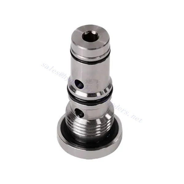
Хидравличен клапан за совалка от серия KSF

Хидравличният клапан с превключване от серията KSF е високопроизводителен компонент, предназначен да подобри контрола на потока на флуиди в хидравличните системи. Със своя усъвършенстван дизайн и здрава конструкция, този клапан предлага прецизна и надеждна работа, осигурявайки оптимална производителност на системата.
Хидравличният вентил от серията KSF е изключително решение за контрол на потока на флуиди в хидравлични системи. Със своята функционалност на вентила, здрава конструкция, висок дебит и компактен дизайн, този вентил оптимизира производителността и осигурява ефективно използване на хидравличната мощност. Спазвайки препоръчителните методи за употреба и практики за поддръжка, хидравличният вентил от серията KSF осигурява надеждна работа и удължава живота на хидравличните системи. Надстройте вашата хидравлична система с хидравличния вентил от серията KSF и се насладете на подобрен контрол на потока на флуиди за подобрена цялостна производителност на системата.
Основни характеристики на хидравличния клапан за совалка от серия KSF:
- Функционалност на совалковия клапан:
- Серията клапани KSF включва конструкция на превключващ клапан за пренасочване на потока на хидравлична течност между два кръга.
- Това позволява избор на верига с по-високо налягане, осигурявайки ефективно използване на хидравличната мощност и предотвратявайки дисбаланс на налягането.
- Здрава конструкция:
- Изработен от издръжливи материали, хидравличният клапан от серията KSF е проектиран да издържа на среди с високо налягане и взискателни работни условия.
- Здравата му конструкция гарантира дълготрайност и надеждност, като минимизира времето за престой и разходите за поддръжка.
- Висок дебитен капацитет:
- Серията клапани KSF предлага висок дебит, което позволява ефикасен пренос на хидравлична течност между веригите.
- Това минимизира падовете на налягането, осигурявайки максимално подаване на мощност и производителност на системата.
- Компактен и универсален дизайн:
- The valve’s compact design makes it suitable for installations with limited space or weight constraints.
- Неговата гъвкавост позволява лесна интеграция в различни хидравлични системи, включително промишлени машини, мобилно оборудване и силови агрегати.
Параметър на хидравличния клапан за совалка от серия KSF:
| Размер | НГ6 | НГ10 | |
| Диапазон на температурата на флуида | ℃ | -30 до +80 (уплътнения от NBR) | |
| -20 до +80 (уплътнения от FKM) | |||
| Диапазон на вискозитет | мм2/с | Препоръка 30~80, разрешение 20~380 | |
| Максимално работно налягане | бар | 350 | |
| Максимален дебит | л/мин | 40 | 60 |
| Тегло | кг | 0.5 | 0.8 |
| Течност | Минерално масло, подходящо за уплътнения от NBR и FKM | ||
| Фосфатен естер за FKM уплътнение | |||
| Степен на замърсяване | Максимално допустима степен на замърсяване на флуида: Клас 9. NAS 1638 или 20/18/15, ISO4406 | ||
Предимства на хидравличния клапан за совалка от серия KSF:
• Уплътнение без течове
• Патронна конструкция за монтаж на маслен блок
Метод на употреба на хидравличен клапан за совалка от серия KSF:
- Системен анализ:
- Преди монтажа, извършете цялостен анализ на хидравличната система, за да определите специфичните изисквания и работните параметри.
- Вземете предвид фактори като дебит, номинално налягане и съвместимост с хидравличния клапан за совалка от серията KSF.
- Избор на клапан:
- Choose the appropriate KSF series valve variant based on the system’s requirements and specifications.
- Вземете предвид фактори като дебит, номинално налягане и съвместимост с други системни компоненти.
- Монтаж:
- Follow the manufacturer’s instructions for properly installing the KSF series shuttle hydraulic Valve in the hydraulic system.
- Осигурете сигурно прилягане, правилно подравняване с пътя на потока на флуида и адекватно уплътнение, за да предотвратите течове.
- Свързване на веригата:
- Свържете входния и изходния отвор на клапана към съответните вериги, които изискват отклоняване на флуида.
- Осигурете правилна идентификация и свързване на веригата за високо налягане и веригата за ниско налягане.
Как работи хидравличният клапан за регулиране на потока?
A hydraulic flow control valve is a device used to regulate and control the speed of hydraulic fluid within a hydraulic system. It allows the operator to adjust the flow rate of the liquid, thereby preventing the speed of hydraulic actuators or controlling the rate of energy transfer. Here’s an explanation of how a hydraulic flow control valve works:
- Структура на клапана:
- Хидравличният регулиращ дебит вентил обикновено се състои от тяло на вентила с входни и изходни отвори, подвижна макара или тарелка и задействащ механизъм.
- Корпусът на клапана съдържа вътрешни проходи и камери, които контролират потока на хидравличната течност.
- Пътища на потока на флуида:
- Регулаторният вентил за поток има входен отвор, който се свързва с хидравличния източник на енергия, като например помпа, и изходен отвор, който се свързва с хидравличния задвижващ механизъм или друг компонент.
- Вентилът осигурява различни пътища на потока на флуида, което позволява той да бъде контролиран и регулиран.
- Макара или тарелка:
- Корпусът на клапана съдържа подвижна макара или тарелка, която регулира потока на хидравлична течност.
- Макарата може да се плъзга в тялото на клапана, докато тарелката може да се движи линейно или да се върти, за да отваря или затваря специфични проходи.
- Задействащ механизъм:
- Хидравличните клапани за регулиране на дебита могат да се задействат ръчно, електрически или чрез други средства, в зависимост от специфичните изисквания за проектиране и приложение.
- Ръчното задействане включва регулиране на дръжка, копче или лост за позициониране на макарата или тарелката.
- Електрическото задействане използва соленоиди, които получават електрически сигнали за преместване на макарата или тарелката, което позволява дистанционно управление и автоматизация.
- Позиции на клапаните:
- Хидравличният регулатор на потока обикновено има множество позиции, които макарата или тарелката могат да заемат, всяка от които съответства на специфичен дебит.
- Вентилът може да има набор от предварително зададени позиции или да предлага непрекъснато регулиране за фина настройка на дебита.
- С изместването на макарата или тарелката, тя се подравнява със специфични проходи, отваряйки или затваряйки ги, за да контролира потока на течността.
- Регулиране на потока:
- Чрез регулиране на позицията на макарата или тарелката, операторът може да контролира размера на проходите за потока, като по този начин регулира дебита на хидравличната течност.
- Когато проходите са напълно отворени, течността тече свободно, което позволява максимален дебит.
- Частичното затваряне на проходите ограничава потока, намалявайки дебита и контролирайки скоростта на хидравличните задвижващи механизми.
- Компенсация на налягането:
- Някои хидравлични клапани за регулиране на дебита включват механизми за компенсиране на налягането, за да поддържат постоянен дебит, въпреки промените в системното налягане.
- Тези механизми гарантират поддържането на желания дебит, дори когато системата се сблъсква с промени в натоварването или налягането.
Възможности и капацитет на фабриката:
(1) Сглобяване
Разполагаме с първокласна независима платформа за научноизследователска и развойна дейност. Цехът за производство на хидравлични цилиндри разполага с четири полуавтоматични линии за монтаж на повдигащи цилиндри и една автоматична линия за монтаж на накланящи се цилиндри, с проектиран годишен производствен капацитет от 1 милион броя. Цехът за специални цилиндри е оборудван с различни спецификации на полуавтоматична система за почистване и монтаж с проектиран годишен производствен капацитет от 200 000 броя и е оборудван с известно CNC машинно оборудване, обработващ център, специално оборудване за високопрецизна обработка на цилиндри, роботизирана заваръчна машина, автоматична машина за почистване, автоматична машина за монтаж на цилиндри и автоматична производствена линия за боядисване. Съществуващото критично оборудване е повече от 300 комплекта. Оптималното разпределение и ефективното използване на ресурсите на оборудването гарантират изискванията за точност на продуктите и отговарят на висококачествените нужди на продуктите.


(2) Машинна обработка
Машинният цех е оборудван със специализиран струговащ център за наклонени релси, обработващ център, високоскоростна хонингова машина, заваръчен робот и друго свързано оборудване, което може да обработва цилиндрични тръби с максимален вътрешен диаметър 400 мм и максимална дължина 6 метра.


(3) Заваряване


(4) Боядисване и покритие
С малки и средни цилиндрични автоматични линии за боядисване на водна основа, за постигане на автоматично роботизирано товарене и разтоварване и автоматично пръскане, проектният капацитет е 4000 броя на смяна;
Разполагаме и с полуавтоматична линия за производство на бои за големи цилиндри, задвижвана от силова верига, с проектен капацитет от 60 каси на смяна.


(5) Тестване
Разполагаме с първокласни инспекционни съоръжения и тестови стендове, за да гарантираме, че производителността на цилиндъра отговаря на изискванията.


Ние сме едни от най-добрите производители на хидравлични цилиндри. Можем да предложим цялостни хидравлични цилиндри. Предлагаме и съответните... селскостопански скоростни кутииИзнасяме продуктите си за клиенти по целия свят и сме си спечелили добра репутация благодарение на превъзходното качество на продуктите и следпродажбеното обслужване. Приветстваме клиенти от страната и чужбина да се свържат с нас, за да преговарят за бизнес, да обменят информация и... сътрудничете с нас!