MG/MK серия дроселова клапа и хидравличен клапан за проверка на дросела
Като един от производителите, доставчиците и износителите на хидравлични цилиндри, ние предлагаме хидравлични цилиндри и много други продукти.
Моля, свържете се с нас за подробности.
Поща:sales@hydraulic-cylinders.net
Производител, доставчик и износител на хидравлични цилиндри.
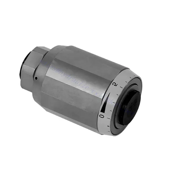
MG/MK серия дроселова клапа и хидравличен клапан за проверка на дросела
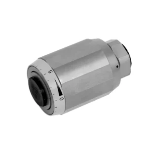
The MG/MK series throttle and throttle check hydraulic valve is a versatile and high-performance hydraulic component designed to optimize control and efficiency in hydraulic systems. With its unique throttle and throttle check functionality, this valve offers precise flow control and ensures the smooth operation of hydraulic actuators.
The MG/MK series throttle and throttle check hydraulic valve is a versatile and reliable solution for precise flow control and enhanced system efficiency. With its throttle functionality, throttle check feature, and customizable flow control options, this valve delivers exceptional performance in various hydraulic applications. Following the recommended usage methods and maintenance guidelines, operators can ensure the longevity, reliability, and optimal functionality of the MG/MK series throttle and check hydraulic valve. Upgrade your hydraulic system with this advanced valve and experience enhanced control, efficiency, and productivity.
MG/MK Series Throttle And Throttle Check Hydraulic Valve Key Characteristics:
- Функционалност на дросела:
- The MG/MK series valve features a throttle function that regulates the flow rate of hydraulic fluid.
- It allows for precise control of the fluid flow, enabling fine-tuning of actuator speed and responsiveness.
- Функция за проверка на дросела:
- В допълнение към управлението на дросела, този клапан включва функция за проверка на дросела.
- The throttle check feature enables the valve to act as a check valve, preventing reverse flow and maintaining system stability.
- Flow Control Versatility:
- The MG/MK Series Valve offers a wide range of flow control options, allowing customization to suit specific application requirements.
- It can be configured for varying flow rates, pressure differentials, and actuator sizes, ensuring compatibility with diverse hydraulic systems.
- Подобрена системна ефективност:
- Чрез осигуряване на прецизен контрол на потока, вентилът минимизира загубите на енергия и оптимизира цялостната ефективност на системата.
- It allows operators to match the hydraulic flow to the specific load requirements, reducing unnecessary power consumption.
- Надеждна производителност:
- The MG/MK Series Valve is built to withstand demanding operating conditions and deliver consistent performance.
- Its robust construction and high-quality materials ensure durability and reliability in various applications.
MG/MK Series Throttle And Throttle Check Hydraulic Valve Parameter:
| Размер | 6 | 8 | 10 | 15 | 20 | 25 | 30 | |
| Тегло | кг | 0.3 | 0.4 | 0.7 | 1.3 | 2.2 | 3.6 | 4.5 |
| Максимално работно налягане | бар | 315bar | ||||||
| Cracking pressure for type MK | бар | 0.5 | ||||||
| Максимален дебит | л/мин | 400 | ||||||
| Диапазон на вискозитет | мм2/с | от 10 до 800 | ||||||
| Диапазон на температурата на флуида | ℃ | -30℃ to +80℃ | ||||||
| Течност | Минерално масло; Фосфатен естер | |||||||
| Степен на замърсяване | Максимално допустима степен на замърсяване на флуида: Клас 9. NAS 1638 или 20/18/15, ISO4406 | |||||||
MG/MK Series Throttle And Throttle Check Hydraulic Valve Advantages:
• Used in direct tubing installation
• Related to pressure and viscosity
Usage Method Of MG/MK Series Throttle And Throttle Check Hydraulic Valve:
- Оценка на системата:
- Assess the hydraulic system’s requirements, including flow rates, pressure differentials, and actuator specifications.
- Identify the need for throttle and throttle check functionality in the system.
- Избор на клапан:
- Select the appropriate variant of the MG/MK series valve based on system parameters and desired flow control characteristics.
- Consider factors such as maximum flow rate, pressure rating, and compatibility with other system components.
- Монтаж:
- Follow the manufacturer’s installation instructions and ensure proper alignment and connection of the valve.
- Pay attention to flow direction arrows and ensure secure fittings and seals.
- Регулиране на потока:
- Adjust the throttle setting on the valve to achieve the desired flow rate.
- Fine-tune the throttle control to optimize actuator performance and system efficiency.
How Hydraulic Control Valve Works?
A hydraulic control valve is a critical component in hydraulic systems that regulates the flow and pressure of hydraulic fluid. It serves as a control mechanism for directing fluid to different hydraulic actuators and controlling the speed and direction of their movement. The operation of a hydraulic control valve can be described as follows:
- Структура на клапана:
- A hydraulic control valve comprises a valve body that houses various internal components, such as spools, poppets, or discs.
- Корпусът на клапана съдържа отвори, проходи и камери, които улесняват потока на хидравлична течност.
- Позиции на клапаните:
- Hydraulic control valves typically have multiple positions, including open, closed, and partially open.
- In the closed position, the valve blocks the flow of fluid entirely.
- In the open position, the valve allows fluid to flow freely through specific ports.
- In the partially open position, the valve restricts or controls the flow rate of the fluid.
- Spool Valve Operation:
- Spool valves are commonly used in hydraulic control systems. They consist of a cylindrical spool with lands or channels.
- The spool is positioned within the valve body and can be moved longitudinally.
- By shifting the spool, different lands align with specific ports, enabling or blocking fluid flow to different actuators.
- The movement of the spool is typically achieved using mechanical linkages, solenoids, or hydraulic pressure acting on the spool.
- Poppet Valve Operation:
- Poppet valves are another type of hydraulic control valve. They use a movable poppet or disc to control fluid flow.
- When the poppet is in the closed position, it rests against a seat, blocking fluid flow.
- To open the valve, the poppet is moved away from the seat, allowing fluid to flow through the passage.
- The movement of the poppet can be achieved through mechanical linkages or hydraulic pressure.
- Механизми за контрол:
- Hydraulic control valves can be operated manually, mechanically, or through electrical means.
- Manual control involves the use of levers, knobs, or handles to position the valve element.
- Mechanical control utilizes mechanical linkages or actuators to move the valve element.
- Electrical control employs solenoids or other electrically controlled devices to shift the valve element.
- Actuator Control:
- Hydraulic control valves direct fluid to various hydraulic actuators, such as cylinders or motors.
- By controlling the valve positions, the hydraulic system can regulate the speed, direction, and force of the actuators.
- For example, adjusting the valve position can control the extension or retraction of a hydraulic cylinder.
- System Stability and Safety:
- Hydraulic control valves play a crucial role in maintaining system stability and safety.
- Pressure relief valves are often incorporated into hydraulic control systems to protect against overpressure.
- These relief valves divert excess fluid to a low-pressure outlet, preventing damage to the system.
Възможности и капацитет на фабриката:
(1) Сглобяване
Разполагаме с първокласна независима платформа за научноизследователска и развойна дейност. Цехът за производство на хидравлични цилиндри разполага с четири полуавтоматични линии за монтаж на повдигащи цилиндри и една автоматична линия за монтаж на накланящи се цилиндри, с проектиран годишен производствен капацитет от 1 милион броя. Цехът за специални цилиндри е оборудван с различни спецификации на полуавтоматична система за почистване и монтаж с проектиран годишен производствен капацитет от 200 000 броя и е оборудван с известно CNC машинно оборудване, обработващ център, специално оборудване за високопрецизна обработка на цилиндри, роботизирана заваръчна машина, автоматична машина за почистване, автоматична машина за монтаж на цилиндри и автоматична производствена линия за боядисване. Съществуващото критично оборудване е повече от 300 комплекта. Оптималното разпределение и ефективното използване на ресурсите на оборудването гарантират изискванията за точност на продуктите и отговарят на висококачествените нужди на продуктите.


(2) Машинна обработка
Машинният цех е оборудван със специализиран струговащ център за наклонени релси, обработващ център, високоскоростна хонингова машина, заваръчен робот и друго свързано оборудване, което може да обработва цилиндрични тръби с максимален вътрешен диаметър 400 мм и максимална дължина 6 метра.

(3) Заваряване

(4) Боядисване и покритие
С малки и средни цилиндрични автоматични линии за боядисване на водна основа, за постигане на автоматично роботизирано товарене и разтоварване и автоматично пръскане, проектният капацитет е 4000 броя на смяна;
Разполагаме и с полуавтоматична линия за производство на бои за големи цилиндри, задвижвана от силова верига, с проектен капацитет от 60 каси на смяна.


(5) Тестване
Разполагаме с първокласни инспекционни съоръжения и тестови стендове, за да гарантираме, че производителността на цилиндъра отговаря на изискванията.

Ние сме едни от най-добрите производители на хидравлични цилиндри. Можем да предложим цялостни хидравлични цилиндри. Предлагаме и съответните... селскостопански скоростни кутииИзнасяме продуктите си за клиенти по целия свят и сме си спечелили добра репутация благодарение на превъзходното качество на продуктите и следпродажбеното обслужване. Приветстваме клиенти от страната и чужбина да се свържат с нас, за да преговарят за бизнес, да обменят информация и... сътрудничете с нас!
Приложение на хидравличния цилиндър:
