

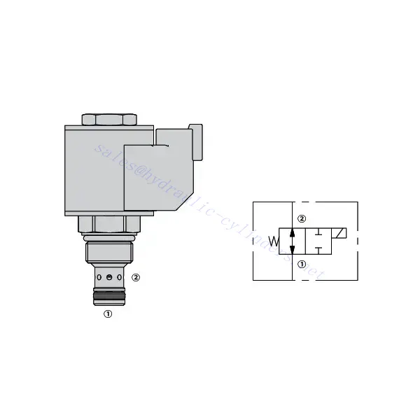
30SD08-25 Solenoid Directional Valve


Welcome to the world of precision hydraulic control with the 30SD08-25 solenoid directional valve. Designed to meet the demands of diverse industrial applications, this cutting-edge valve offers exceptional performance, reliability, and efficiency.
The 30SD08-25 solenoid directional valve is your gateway to enhanced hydraulic control. With its precise fluid flow management, versatility, high flow capacity, and quick response time, this valve empowers your hydraulic system to reach new levels of performance and efficiency. By following the recommended usage methods and maintenance guidelines, you can harness the full potential of the 30SD08-25 solenoid directional valve and achieve seamless control, increased productivity, and improved overall performance. Elevate your hydraulic system today with the 30sd08-25 solenoid directional valve and experience the power of precise hydraulic control.
30SD08-25 Solenoid Directional Valve Characteristics:
- Precise Fluid Flow Management:
- The 30SD08-25 solenoid directional valve empowers you with precise control over fluid flow in your hydraulic system.
- With its accurate flow management capabilities, this valve ensures optimal performance and responsiveness.
- Všestranné aplikace:
- This valve is designed to cater to various industrial applications, making it a versatile solution for hydraulic systems.
- Whether you require precise control in manufacturing, construction, or automation, the 30SD08-25 solenoid directional valve delivers the needed performance.
- Vysoká průtoková kapacita:
- With its high flow capacity, this valve can handle significant fluid volumes, enabling efficient and reliable operation.
- The valve’s ability to accommodate high flow rates ensures that your hydraulic system operates smoothly, even in demanding conditions.
- Rychlá doba odezvy:
- Equipped with state-of-the-art solenoid technology, the 30SD08-25 solenoid directional valve boasts an impressive response time.
- Experience rapid and accurate control adjustments, allowing seamless fluid flow direction changes and improved system efficiency.
30SD08-25 Solenoid Directional Valve Parameter:
| Jmenovitý tlak | 207 barů (3000 psi) | |
| Vrcholový průtok | 9.5 L/min (2.5 gpm) | |
| Vnitřní únik | ≤ 82 mL/min @207 bar | |
| Jmenovité zatížení cívky | Plynulý od 85% do 115% jmenovitého napětí | |
| Počáteční odběr proudu cívky při 20 °C | 1,4 A při 12 V DC; 0,7 A při 24 V DC | |
| Minimální přítahové napětí | 85% jmenovitého tlaku 207 barů (3000 psi) | |
| Dutina | VC08-2 | |
| Tekutina | Minerální nebo syntetické oleje s mazacími vlastnostmi | |
| Rozsah teploty kapaliny ℃ | -54 až 107 ℃ (polyuretanová těsnění) | |
| -40 až 100 ℃ (těsnění Buna N) | ||
| -26 až 204 ℃ (těsnění z fluorokarbonu) | ||
| Rozsah viskozity | 7,4 až 420 mm2/s | |
| Stupeň kontaminace | Minimální úroveň znečištění je dle normy ISO4406 20/18/14 a pro prodloužení životnosti se doporučuje úroveň 17/15/13. | |
30SD08-25 Solenoid Directional Valve Advantages:
• Cívka s trvalým provozem
• Both ports may be fully pressurized
• Efektivní konstrukce s mokrou armaturou
• Kazety jsou napěťově vyměnitelné
• Volitelné vodotěsné elektrické cívky s krytím až IP69K
• Běžná dutina v průmyslu
• Kalené díly pro dlouhou životnost a nízkou netěsnost
Usage Method Of 30SD08-25 Solenoid Directional Valve:
- Vyhodnocení systému:
- Begin by evaluating the specific requirements of your hydraulic system, considering factors such as flow rates, pressure levels, and system dynamics.
- Assess whether the 30SD08-25 solenoid directional valve aligns with your system’s needs and performance expectations.
- Výběr ventilu:
- Select the appropriate variant of the 30SD08-25 solenoid directional Valve based on your system parameters and performance requirements.
- Pro optimální funkčnost zvažte faktory, jako je průtoková kapacita, jmenovitý tlak a kompatibilita s dalšími komponenty systému.
- Instalace:
- Follow the manufacturer’s installation instructions diligently to ensure proper placement and secure valve mounting.
- Position the valve correctly within the hydraulic system, considering fluid flow direction and accessibility for maintenance purposes.
- Elektrické připojení:
- Connect the solenoid valve to the designated power source per the manufacturer’s specifications.
- Ensure the electrical connections are secure, adhering to safety standards and regulations.
How To Install A Hydraulic Pressure Relief Valve?
Installing a hydraulic pressure relief valve is a crucial step in ensuring the safety and proper functioning of a hydraulic system. Here’s a step-by-step guide on how to install a hydraulic pressure relief valve:
- Identifikujte ventil: Determine the specific type and model of the hydraulic pressure relief valve you work with. Ensure it is suitable for your application and compatible with your hydraulic system requirements.
- Připravte si potřebné nástroje a materiály: Collect the necessary tools and materials, including appropriate hydraulic fittings, adapters, wrenches, Teflon tape (thread sealant), and a pressure gauge if needed. Refer to the manufacturer’s instructions for any specific tools or components required.
- Příprava hydraulického systému: Vypněte hydraulický systém a uvolněte tlak aktivací pojistného ventilu nebo zasunutím hydraulických válců. Tento krok je zásadní pro bezpečnost a zabraňuje náhodnému pohybu nebo úniku hydraulické kapaliny.
- Identify the Pressure Relief Point: Determine the optimal location to install the hydraulic pressure relief valve in your hydraulic system. It should be positioned downstream of the pump before any sensitive components to protect them from excessive pressure. Consult the hydraulic system schematic or seek professional advice if necessary.
- Namontujte ventil: Securely mount the hydraulic pressure relief valve in the chosen location using appropriate brackets or clamps. Ensure the valve is positioned correctly, aligning the inlet and outlet ports with the flow direction. Follow the manufacturer’s instructions for specific mounting requirements.
- Připojte vstupní a výstupní porty: Attach hydraulic hoses or tubing to the inlet and outlet ports of the relief valve. Use suitable hydraulic fittings and adapters to create a leak-free connection. Apply Teflon tape or thread sealant to the male threads of the fittings to ensure a secure and sealed connection. Tighten the connections using wrenches to avoid leaks, but be careful not to overtighten.
- Set the Pressure Relief Setting: Most hydraulic pressure relief valves come with an adjustable pressure relief setting. Adjust the relief valve to the desired pressure relief point using the manufacturer’s guidelines. Some valves may require a pressure gauge to accurately set the relief pressure. Install the pressure gauge temporarily, if needed, and adjust the relief valve until the desired pressure is achieved.
- Otestujte systém: Once the hydraulic pressure relief valve is installed, slowly restore hydraulic system pressure. Monitor the pressure gauge or observe the system behavior to ensure that the relief valve functions correctly. The relief valve should open and divert excess pressure when it reaches the set point, preventing damage to the system.
- Monitorování a údržba: Regularly inspect the hydraulic pressure relief valve for any signs of leakage, damage, or reduced performance. Clean the valve and surrounding area to remove dirt and debris that may affect its operation. Follow the manufacturer’s recommended maintenance schedule and guidelines to ensure optimal performance and longevity.
Schopnosti a kapacita továrny:
(1) Montáž
Disponujeme prvotřídní nezávislou výzkumnou a vývojovou montážní platformou. Dílna na výrobu hydraulických válců má čtyři poloautomatické montážní linky pro zvedací válce a jednu automatickou montážní linku pro naklápěcí válce s projektovanou roční výrobní kapacitou 1 milion kusů. Dílna na speciální válce je vybavena poloautomatickým čisticím montážním systémem s různými specifikacemi a projektovanou roční výrobní kapacitou 200 000 kusů a je vybavena známým CNC obráběcím zařízením, obráběcím centrem, vysoce přesným speciálním zařízením pro zpracování válců, robotickým svařovacím strojem, automatickým čisticím strojem, automatickým montážním strojem pro válce a automatickou lakovací výrobní linkou. Stávající kritické vybavení má více než 300 sad. Optimální alokace a efektivní využití zdrojů zařízení zajišťuje požadavky na přesnost výrobků a splňuje požadavky na vysokou kvalitu výrobků.


(2) Obrábění
Obrobna je vybavena zakázkovým soustružnickým centrem pro šikmé kolejnice, obráběcím centrem, vysokorychlostním honovacím strojem, svařovacím robotem a dalším souvisejícím zařízením, které zvládne obrábění válcových trubek s maximálním vnitřním průměrem 400 mm a maximální délkou 6 metrů.


(3) Svařování


(4) Lakování a nátěry
S malými a středními válcovými automatickými linkami na nanášení barev na vodní bázi, pro dosažení automatického robotického nakládání a vykládání a automatického stříkání, je konstrukční kapacita 4000 kusů za směnu;
Máme také poloautomatickou linku na výrobu barev pro velké tlakové lahve poháněné řetězem s konstrukční kapacitou 60 lahví za směnu.


(5) Testování
Disponujeme prvotřídními inspekčními zařízeními a zkušebními laboratořemi, abychom zajistili, že výkon válce splňuje požadavky.


Jsme jedním z nejlepších výrobců hydraulických válců. Nabízíme komplexní hydraulické válce. Dodáváme také odpovídající zemědělské převodovkyNaše výrobky jsme exportovali klientům po celém světě a díky vynikající kvalitě výrobků a poprodejnímu servisu jsme si získali dobrou pověst. Vítáme zákazníky doma i v zahraničí, kteří nás kontaktují za účelem vyjednávání obchodních příležitostí, výměny informací a spolupracujte s námi!