30SD38-38 Solenoid Directional Valve
Jako jeden z výrobců, dodavatelů a vývozců hydraulických válců nabízíme hydraulické válce a mnoho dalších výrobků.
Kontaktujte nás, prosím, pro podrobnosti.
Mail:sales@hydraulic-cylinders.net
Výrobce, dodavatel a vývozce hydraulických válců.
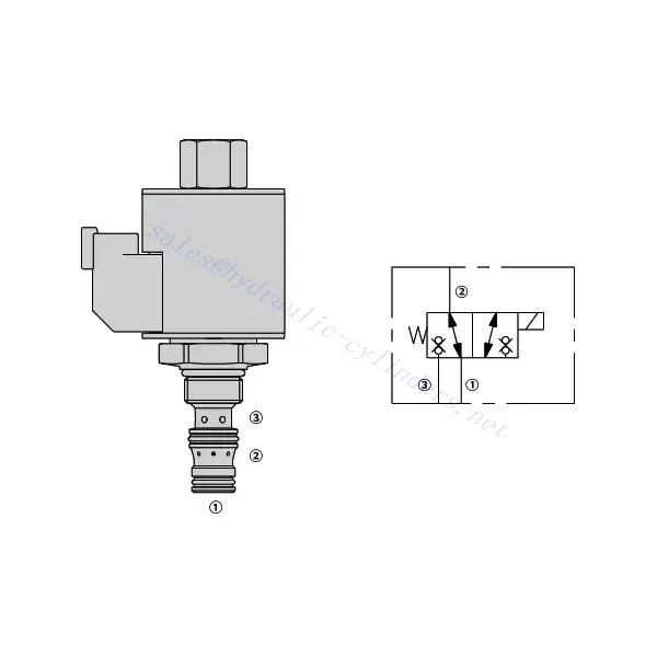
30SD38-38 Solenoid Directional Valve
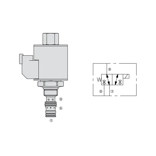
The 30SD38-38 solenoid directional valve is a highly efficient and versatile component that plays a pivotal role in fluid control systems. This valve is designed to deliver precise and reliable fluid control and offers exceptional performance and durability.
The 30SD38-38 solenoid directional valve is a reliable and efficient fluid control solution for various industrial applications. With its robust construction, efficient performance, and versatile mounting options, this valve provides precise control over fluid flow and enhances overall system performance. By following proper usage methods and implementing regular maintenance practices, you can ensure optimal functionality and longevity of the 30SD38-38 solenoid directional valve, making it an excellent choice for your fluid control needs.
30SD38-38 Solenoid Directional Valve Characteristics:
- Robust Construction: The 30SD38-38 solenoid directional valve is constructed with high-quality materials, ensuring durability and resistance to wear and corrosion. Its rugged design allows it to withstand harsh operating conditions, making it suitable for various industrial applications.
- Efficient Performance: Powered by a solenoid, this valve provides rapid response times, enabling quick adjustments to fluid flow and pressure. The efficient operation ensures precise control and seamless integration into automated processes.
- Versatile Mounting Options: The valve offers flexible mounting options, including inline, manifold, or subplate configuration. This versatility allows for easy installation and integration into various fluid control systems, accommodating different application requirements.
30SD38-38 Solenoid Directional Valve Parameter:
| Jmenovitý tlak | 207 barů (3000 psi) | |
| Vrcholový průtok | Viz graf výkonu | |
| Vnitřní únik | ≤5 drops/min@207bar | |
| Jmenovité zatížení cívky | Plynulý od 85% do 115% jmenovitého napětí | |
| Počáteční odběr proudu cívky při 20 °C | E-cívka | 1,7 A při 12 V DC; 0,85 A při 24 V DC |
| D-cívka | 1,67 A při 12 V DC; 0,83 A při 24 V DC | |
| Minimální přítahové napětí | 85% jmenovitého tlaku 207 barů (3000 psi) | |
| Dutina | VC08-3 | |
| Tekutina | Minerální nebo syntetické oleje s mazacími vlastnostmi | |
| Rozsah teploty kapaliny ℃ | -54 až 107 ℃ (polyuretanová těsnění) | |
| -40 až 100 ℃ (těsnění Buna N) | ||
| -26 až 204 ℃ (těsnění z fluorokarbonu) | ||
| Rozsah viskozity | 7,4 až 420 mm2/s | |
| Stupeň kontaminace | Minimální úroveň znečištění je dle normy ISO4406 20/18/14 a pro prodloužení životnosti se doporučuje úroveň 17/15/13. | |
30SD38-38 Solenoid Directional Valve Advantages:
• Cívka s trvalým provozem
• Kazety jsou napěťově vyměnitelné
• Volitelné vodotěsné elektrické cívky s krytím až IP69K
• Efektivní konstrukce s mokrou armaturou
• Běžná dutina v průmyslu
• Kalené díly pro dlouhou životnost
Usage Method Of 30SD38-38 Solenoid Directional Valve:
- Determine the application requirements: Identify the specific fluid control needs of your system. Consider factors such as flow rate, pressure, and direction to select the appropriate valve configuration.
- Mount the valve: Choose the suitable mounting option based on your system’s layout and available space. Ensure that the valve is securely positioned and aligned with the fluid lines.
- Connect the fluid lines: Use compatible fittings and connectors to establish the necessary connections between the valve and the fluid lines. Ensure tight and leak-free connections.
- Electrical connection: Connect the solenoid valve to the appropriate power source following the manufacturer’s instructions. Ensure proper wiring and observe safety precautions.
- Test and adjust: Once the valve is installed and connected, gradually introduce fluid flow and monitor its behavior. Test different operating conditions and adjust the valve settings as needed to achieve the desired fluid control.
How To Replace A Shower Mixing Valve Cartridge?
Replacing a shower mixing valve cartridge is a common DIY task that can help restore proper water temperature and flow control. Here’s a step-by-step guide on how to replace a shower mixing valve cartridge:
- Gather the necessary tools: Before starting the replacement process, gather the following tools: adjustable wrench, Phillips screwdriver, flathead screwdriver, pliers, Allen wrench (if applicable), and a replacement cartridge specific to your shower valve model.
- Turn off the water supply: Locate the main water shut-off valve for your home and turn it off to stop the water flow to the shower. If there isn’t a dedicated shut-off valve for the shower, you may need to shut off the main water supply.
- Remove the handle and trim: Start by removing the handle. Depending on the type of handle, you may need to locate a set screw or a decorative cap covering the screw. Use a flathead or Phillips screwdriver to remove the screw or pry off the cap, allowing you to detach the handle. Next, remove any trim or decorative coverings around the valve by gently pulling or unscrewing them.
- Access the cartridge: Depending on the valve design, you may need to remove additional components to access the cartridge. This can include a retaining nut, sleeve, or escutcheon plate. Use the appropriate tools to remove these components and expose the cartridge.
- Remove the old cartridge: Once you have clear access to the cartridge, use pliers or a specialized cartridge removal tool, if provided, to carefully pull out the old cartridge. Wiggle it back and forth if necessary. Be cautious not to damage any surrounding plumbing connections.
- Clean the valve body: Before installing the new cartridge, clean the valve body thoroughly to remove any debris or mineral buildup. Wipe it with a clean cloth or use a mild cleaning solution if needed.
- Install the new cartridge: Take the replacement cartridge and align it with the valve body, ensuring that any tabs or notches match up correctly. Push the cartridge firmly into place until it sits flush with the valve body.
- Reassemble the valve: Put back any components you removed earlier, such as the retaining nut, sleeve, or escutcheon plate. Make sure they are tightened securely but avoid overtightening.
- Test for leaks: Turn on the water supply and carefully observe the valve for any leaks. If you notice any leaks, tighten the connections or adjust the cartridge as needed. Check both the hot and cold water settings to ensure proper temperature control.
- Reinstall the trim and handle: Once you’ve confirmed that there are no leaks, reinstall the trim or decorative coverings over the valve. Slide the handle back onto the cartridge stem and secure it with the set screw or by replacing the decorative cap.
- Restore water supply: Finally, turn on the main water supply or the dedicated shut-off valve for the shower and test the functionality of the new cartridge. Verify that the water temperature and flow can be adjusted smoothly.
Schopnosti a kapacita továrny:
(1) Montáž
Disponujeme prvotřídní nezávislou výzkumnou a vývojovou montážní platformou. Dílna na výrobu hydraulických válců má čtyři poloautomatické montážní linky pro zvedací válce a jednu automatickou montážní linku pro naklápěcí válce s projektovanou roční výrobní kapacitou 1 milion kusů. Dílna na speciální válce je vybavena poloautomatickým čisticím montážním systémem s různými specifikacemi a projektovanou roční výrobní kapacitou 200 000 kusů a je vybavena známým CNC obráběcím zařízením, obráběcím centrem, vysoce přesným speciálním zařízením pro zpracování válců, robotickým svařovacím strojem, automatickým čisticím strojem, automatickým montážním strojem pro válce a automatickou lakovací výrobní linkou. Stávající kritické vybavení má více než 300 sad. Optimální alokace a efektivní využití zdrojů zařízení zajišťuje požadavky na přesnost výrobků a splňuje požadavky na vysokou kvalitu výrobků.


(2) Obrábění
Obrobna je vybavena zakázkovým soustružnickým centrem pro šikmé kolejnice, obráběcím centrem, vysokorychlostním honovacím strojem, svařovacím robotem a dalším souvisejícím zařízením, které zvládne obrábění válcových trubek s maximálním vnitřním průměrem 400 mm a maximální délkou 6 metrů.

(3) Svařování

(4) Lakování a nátěry
S malými a středními válcovými automatickými linkami na nanášení barev na vodní bázi, pro dosažení automatického robotického nakládání a vykládání a automatického stříkání, je konstrukční kapacita 4000 kusů za směnu;
Máme také poloautomatickou linku na výrobu barev pro velké tlakové lahve poháněné řetězem s konstrukční kapacitou 60 lahví za směnu.


(5) Testování
Disponujeme prvotřídními inspekčními zařízeními a zkušebními laboratořemi, abychom zajistili, že výkon válce splňuje požadavky.

Jsme jedním z nejlepších výrobců hydraulických válců. Nabízíme komplexní hydraulické válce. Dodáváme také odpovídající zemědělské převodovkyNaše výrobky jsme exportovali klientům po celém světě a díky vynikající kvalitě výrobků a poprodejnímu servisu jsme si získali dobrou pověst. Vítáme zákazníky doma i v zahraničí, kteří nás kontaktují za účelem vyjednávání obchodních příležitostí, výměny informací a spolupracujte s námi!
Použití hydraulického válce:
