

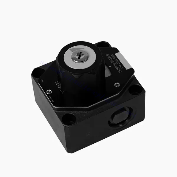
Hydraulický ventil pro regulaci průtoku řady FRM

Hydraulický ventil pro regulaci průtoku řady FRM je špičkový hydraulický komponent navržený pro zvýšení výkonu a ovládání hydraulických systémů. Díky svým pokročilým funkcím a spolehlivé funkčnosti nabízí tento ventil přesnou regulaci průtoku a optimální účinnost.
Hydraulický ventil pro regulaci průtoku řady FRM je spolehlivým a všestranným řešením pro optimalizaci regulace průtoku v hydraulických systémech. Díky přesným možnostem regulace průtoku, stabilitě tlaku a teploty a odolné konstrukci nabízí tento ventil vylepšený výkon a účinnost. Při dodržování doporučených metod používání a pokynů pro údržbu mohou operátoři maximalizovat výhody hydraulického ventilu pro regulaci průtoku řady FRM a zajistit tak plynulý provoz a spolehlivou regulaci průtoku v hydraulických aplikacích. Vylepšete svůj hydraulický systém tímto pokročilým ventilem a zažijte přesnost, účinnost a produktivitu jako nikdy předtím.
Klíčové vlastnosti hydraulického ventilu pro regulaci průtoku řady FRM:
- Přesnost regulace průtoku:
- Ventil řady FRM umožňuje přesné řízení průtoku hydraulických kapalin, což obsluze umožňuje jemně doladit a regulovat rychlost pohonů.
- Díky své výjimečné přesnosti zajišťuje tento ventil konzistentní regulaci průtoku, což vede ke zlepšení výkonu systému a zvýšení produktivity.
- Všestranné použití:
- Ventil řady FRM je vysoce všestranný a kompatibilní s různými hydraulickými systémy, včetně průmyslových strojů, stavebních zařízení a mobilních aplikací.
- Díky své přizpůsobivosti je ideální volbou pro širokou škálu hydraulických sestav a poskytuje spolehlivou a efektivní regulaci průtoku.
- Stabilita tlaku a teploty:
- Tento hydraulický ventil je navržen tak, aby udržoval konzistentní regulaci průtoku i za proměnlivých tlakových a teplotních podmínek.
- Zajišťuje stabilní výkon a zabraňuje kolísání průtoku, čímž chrání integritu a spolehlivost hydraulického systému.
- Odolná konstrukce:
- Ventil řady FRM je vyroben z vysoce kvalitních materiálů, což zaručuje odolnost a dlouhodobou spolehlivost v náročných provozních prostředích.
- Jeho robustní konstrukce umožňuje odolávat vysokým tlakům, vibracím a teplotním extrémům, což poskytuje spolehlivé řešení pro hydraulické aplikace.
Parametr hydraulického ventilu pro regulaci průtoku řady FRM:
NG6
| Regulační ventil průtoku | |||||||||||
| Max. provozní tlak - port A | bar | 315 | |||||||||
| Tlakový rozdíl ΔP pro volný zpětný tok B do A | Viz charakteristické křivky | ||||||||||
| Minimální tlakový rozdíl | bar | 6 až 14 | |||||||||
| Tlaková stabilita až do P= 315 barů | % | ±2(Qmax) | |||||||||
| Tok | Qmax | l/min | 0.2 | 0.6 | 1.5 | 3 | 6 | 10 | 16 | 25 | 32 |
| Qmin až 100 barů | ml/min | 15 | 15 | 15 | 15 | 25 | 50 | 70 | 100 | 250 | |
| Qmin až 315 barů | 25 | 25 | 25 | 25 | 25 | 50 | 70 | 100 | 250 | ||
| Tekutina | Minerální olej, fosfátový ester | ||||||||||
| Rozsah teplot kapaliny | ℃ | – 20 až + 80 | |||||||||
| Rozsah viskozity | mm2/s | 10 až 800 | |||||||||
| Stupeň kontaminace | Maximální přípustný stupeň znečištění kapaliny: Třída 9. NAS 1638 nebo 20/18/15, ISO4406 | ||||||||||
| Montážní poloha | Volitelný | ||||||||||
| Teplotní rozsah okolností | ℃ | -20 až +50 | |||||||||
| Hmotnost | 2FRM6A…2FRM6B… | kg | asi 1,3 | ||||||||
| 2FRM6SB… | kg | asi 1,5 | |||||||||
| Usměrňovače | |||||||||||
| Jmenovitý průtok | bar | 320 | |||||||||
| Max. provozní tlak | bar | na 210 | |||||||||
| Tlak v trhlinách | bar | 0.7 | |||||||||
| Hmotnost | kg | asi 0,9 | |||||||||
NG5/10/16
| Regulační ventil průtoku | ||||||||||||||||
| Max. provozní tlak - port A | bar | 315 | ||||||||||||||
| Tlakový rozdíl ΔP pro volný zpětný tok B do A | Viz charakteristické křivky | |||||||||||||||
| Minimální tlakový rozdíl | bar | 6 až 14 | ||||||||||||||
| Tekutina | Minerální olej, fosfátový ester | |||||||||||||||
| Rozsah teplot kapaliny | ℃ | – 20 až + 80 | ||||||||||||||
| Rozsah viskozity | mm2/s | 10 až 800 | ||||||||||||||
| Stupeň kontaminace | Maximální přípustný stupeň znečištění kapaliny: Třída 9. NAS 1638 nebo 20/18/15, ISO4406 | |||||||||||||||
| Velikost | mm | 5 | 10 | 16 | ||||||||||||
| Max. průtok | l/min | 0.2 | 0.6 | 1.2 | 3 | 6 | 10 | 15 | 10 | 16 | 25 | 50 | 60 | 100 | 160 | |
| Zpětný tok oleje B do A | ml/min | 0.5 | 0.5 | 0.6 | 0.9 | 1.8 | 3.6 | 6.7 | 2 | 2.5 | 3.5 | 6 | 2.8 | 4.3 | 7.3 | |
| Rozsah stabilního průtoku (%Qmax) (-20-±80 ℃) | ±5 | ±3 | ±2 | ±2 | ||||||||||||
| ±2 (P=210 barů) | ±2 (P=350 barů) | |||||||||||||||
| Provozní tlak | bar | 210 | 350 | |||||||||||||
| Minimální pokles tlaku | bar | 3-5 | 6-8 | 3-7 | 5-12 | |||||||||||
| Hmotnost | kg | 1.6 | 3.4 | 7.4 | ||||||||||||
| Usměrňovače | ||||||||||||||||
| Tekutina | Minerální olej, fosfátový ester | |||||||||||||||
| Rozsah teplot kapaliny | -20 až +80 | |||||||||||||||
| Rozsah viskozity | 10 až 800 | |||||||||||||||
| Stupeň kontaminace | Maximální přípustný stupeň znečištění kapaliny: Třída 9. NAS 1638 nebo 20/18/15, ISO4406 | |||||||||||||||
| Velikost | 5 | 10 | 16 | |||||||||||||
| Tok | 15 | 50 | 160 | |||||||||||||
| Provozní tlak | 210 | 315 | 315 | |||||||||||||
| Tlak v trhlinách | 1 | 1.5 | 1.5 | |||||||||||||
| Hmotnost | 0.6 | 3.2 | 9.3 | |||||||||||||
Výhody hydraulického ventilu pro regulaci průtoku řady FRM:
• Montáž na základní desku viz katalog produktů
• Omezovač posunutí s kompenzací tlaku, volitelný
• Volitelný jednosměrný ventil
• Knoflík se stupnicí, volitelně uzamykatelný
Způsob použití hydraulického ventilu pro regulaci průtoku řady FRM:
- Vyhodnocení systému:
- Begin by assessing the hydraulic system’s requirements, including flow rates, pressure ranges, and desired flow control parameters.
- Na základě schopností regulace průtoku určete, zda je ventil řady FRM vhodný pro konkrétní aplikaci.
- Výběr ventilu:
- Vyberte vhodnou variantu ventilu řady FRM na základě parametrů systému, požadovaného průtoku a kompatibility s ostatními komponenty systému.
- Zvažte faktory, jako je maximální průtok, jmenovitý tlak a provozní podmínky.
- Instalace:
- Follow the manufacturer’s installation instructions carefully, ensuring proper alignment and secure valve connections.
- Věnujte pozornost ukazatelům směru průtoku a zajistěte správnou polohu ventilu v hydraulickém systému.
- Nastavení regulace průtoku:
- Po instalaci upravte nastavení regulace průtoku ventilu podle požadovaného průtoku a požadavků systému.
- Jemně dolaďte ventil pro dosažení požadované rychlosti a výkonu hydraulických pohonů a optimalizujte tak celkový provoz systému.
Jak fungují hydraulické ventily?
Hydraulic valves are crucial in controlling the flow and direction of hydraulic fluid within a hydraulic system. They are essential components that enable the precise operation of various hydraulic machinery and equipment. Here’s a simplified explanation of how hydraulic valves work:
- Základy hydraulických systémů:
Hydraulické systémy používají kapalinu, obvykle olej, k přenosu výkonu a řízení pohybu mechanických součástí. Tyto systémy se skládají z hydraulického čerpadla, které natlakuje kapalinu, řady ventilů, které řídí tok a směr kapaliny, a hydraulických aktuátorů (jako jsou válce nebo motory), které přeměňují energii kapaliny na mechanickou sílu nebo pohyb. - Typy ventilů:
Existuje řada hydraulických ventilů, včetně směrových regulačních ventilů, tlakových regulačních ventilů, regulačních ventilů průtoku a zpětných ventilů. Každý typ ventilu slouží specifickému účelu při regulaci průtoku kapaliny, tlaku nebo směru. - Rozváděcí ventily:
Rozváděče určují cestu, kterou proudí hydraulická kapalina. Mají několik poloh (například otevřeno, zavřeno nebo částečně otevřeno) a několik otvorů pro směrování kapaliny do různých částí hydraulického systému. - Součásti ventilu:
Hydraulické ventily se obvykle skládají z tělesa ventilu, které obsahuje vnitřní průchody a kanály, a pohyblivého ventilového prvku nebo šoupátka, které se posouvá uvnitř tělesa ventilu. Šoupátko má různé výstupky nebo otvory, které jsou zarovnány s vnitřními průchody pro řízení průtoku kapaliny. - Pohyb cívky:
Poloha šoupátka v tělese ventilu určuje dráhu proudění a v důsledku toho směr proudění kapaliny. Šoupátko lze ovládat různými prostředky, jako jsou mechanické spoje, solenoidy nebo pilotní tlak. - Tlakové regulační ventily:
Regulační ventily tlaku regulují tlak hydraulické kapaliny v systému. Mohou udržovat určitou úroveň tlaku tím, že umožňují přebytečné kapalině návrat do zásobníku nebo blokují průtok, dokud není dosaženo požadovaného tlaku. - Regulační ventily průtoku:
Regulační ventily průtoku řídí rychlost průtoku kapaliny v hydraulickém systému. Mohou být použity k řízení rychlosti hydraulických pohonů nebo k omezení průtoku v určitých částech systému. - Zpětné ventily:
Zpětné ventily neboli jednosměrné ventily umožňují proudění kapaliny jedním směrem a zabraňují zpětnému toku. Zajišťují, aby se kapalina pohybovala požadovaným směrem, a zabraňují nežádoucím poklesům tlaku nebo ztrátě hydraulické síly. - Ovládání ventilu:
Hydraulické ventily lze ovládat ručně, mechanicky nebo elektronicky. Páky nebo knoflíky přímo ovládají ruční ventily, zatímco mechanické a elektronické pohony umožňují automatické ovládání poloh ventilů na základě systémových požadavků. - Ovládání systému:
By combining different types of hydraulic valves and controlling their positions or actuation, the hydraulic system’s overall function can be precisely regulated. This enables operators to control the movement, speed, force, and direction of hydraulic actuators, allowing for precise and efficient operation of hydraulic machinery.
Schopnosti a kapacita továrny:
(1) Montáž
Disponujeme prvotřídní nezávislou výzkumnou a vývojovou montážní platformou. Dílna na výrobu hydraulických válců má čtyři poloautomatické montážní linky pro zvedací válce a jednu automatickou montážní linku pro naklápěcí válce s projektovanou roční výrobní kapacitou 1 milion kusů. Dílna na speciální válce je vybavena poloautomatickým čisticím montážním systémem s různými specifikacemi a projektovanou roční výrobní kapacitou 200 000 kusů a je vybavena známým CNC obráběcím zařízením, obráběcím centrem, vysoce přesným speciálním zařízením pro zpracování válců, robotickým svařovacím strojem, automatickým čisticím strojem, automatickým montážním strojem pro válce a automatickou lakovací výrobní linkou. Stávající kritické vybavení má více než 300 sad. Optimální alokace a efektivní využití zdrojů zařízení zajišťuje požadavky na přesnost výrobků a splňuje požadavky na vysokou kvalitu výrobků.


(2) Obrábění
Obrobna je vybavena zakázkovým soustružnickým centrem pro šikmé kolejnice, obráběcím centrem, vysokorychlostním honovacím strojem, svařovacím robotem a dalším souvisejícím zařízením, které zvládne obrábění válcových trubek s maximálním vnitřním průměrem 400 mm a maximální délkou 6 metrů.


(3) Svařování


(4) Lakování a nátěry
S malými a středními válcovými automatickými linkami na nanášení barev na vodní bázi, pro dosažení automatického robotického nakládání a vykládání a automatického stříkání, je konstrukční kapacita 4000 kusů za směnu;
Máme také poloautomatickou linku na výrobu barev pro velké tlakové lahve poháněné řetězem s konstrukční kapacitou 60 lahví za směnu.


(5) Testování
Disponujeme prvotřídními inspekčními zařízeními a zkušebními laboratořemi, abychom zajistili, že výkon válce splňuje požadavky.


Jsme jedním z nejlepších výrobců hydraulických válců. Nabízíme komplexní hydraulické válce. Dodáváme také odpovídající zemědělské převodovkyNaše výrobky jsme exportovali klientům po celém světě a díky vynikající kvalitě výrobků a poprodejnímu servisu jsme si získali dobrou pověst. Vítáme zákazníky doma i v zahraničí, kteří nás kontaktují za účelem vyjednávání obchodních příležitostí, výměny informací a spolupracujte s námi!