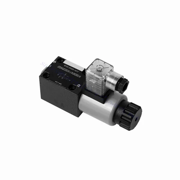
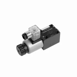
Hydraulický směrový sedlový ventil řady M-SED s elektromagnetickým ovládáním
Jako jeden z výrobců, dodavatelů a vývozců hydraulických válců nabízíme hydraulické válce a mnoho dalších výrobků.
Kontaktujte nás, prosím, pro podrobnosti.
Mail:sales@hydraulic-cylinders.net
Výrobce, dodavatel a vývozce hydraulických válců.
Hydraulický směrový sedlový ventil řady M-SED s elektromagnetickým ovládáním
Hydraulický směrový sedlový ventil řady M-SED s ovládáním solenoidem je špičkovým řešením, které poskytuje přesné ovládání a optimální účinnost v hydraulických systémech. Díky inovativní konstrukci, spolehlivému výkonu a pokročilému ovládání solenoidem nabízí tento ventil vylepšenou regulaci průtoku kapaliny, flexibilitu a kompatibilitu s různými průmyslovými aplikacemi.
Hydraulický směrový sedlový ventil řady M-SED s ovládáním solenoidem je spolehlivým a efektivním řešením pro hydraulické systémy. Díky své konstrukci směrového sedlového ventilu, pokročilému ovládání solenoidem, všestrannosti a vysokému průtoku nabízí tento ventil přesné ovládání, zvýšenou účinnost a kompatibilitu s různými aplikacemi. Ventil řady M-SED poskytuje optimální výkon a spolehlivost při dodržování doporučených metod používání a pravidelných postupů údržby. Vylepšete svůj hydraulický systém směrovým sedlovým hydraulickým ventilem řady M-SED a zažijte vylepšené ovládání, účinnost a produktivitu.
Hydraulický směrový sedlový ventil řady M-SED s elektromagnetickým ovládáním Klíčové vlastnosti:
- Směrový design talířového ventilu:
- Ventil řady M-SED se vyznačuje směrovým talířovým provedením, které zajišťuje spolehlivou a efektivní regulaci průtoku kapaliny.
- Umožňuje rychlou odezvu a přesnou regulaci směru kapaliny, což zlepšuje celkový výkon systému.
- Ovládání solenoidem:
- Tento hydraulický ventil je vybaven pokročilým solenoidovým ovládáním a umožňuje dálkové a automatizované ovládání.
- Solenoid umožňuje rychlé a přesné přepínání mezi různými cestami proudění, což zlepšuje provozní efektivitu.
- Všestrannost a kompatibilita:
- Ventil řady M-SED je vysoce všestranný a kompatibilní s různými hydraulickými systémy a aplikacemi.
- Lze jej bezproblémově integrovat do průmyslových strojů, mobilních zařízení a automatizačních systémů, což zvyšuje jeho výkon.
- Vysoká průtoková kapacita:
- Díky robustní konstrukci a optimalizovaným cestám proudění nabízí ventil řady M-SED vysoký průtok.
- Zajišťuje efektivní přenos kapaliny, snižuje tlakové ztráty a maximalizuje propustnost systému.
Hydraulický směrový sedlový ventil řady M-SED s elektromagnetickým ovládáním Parametr:
| Specifikace | NG6 | NG10 | ||
| Montážní poloha | Volitelný | |||
| Teplota prostředí | ℃ | -30 až +50 (těsnění NBR) | ||
| -20 až +50 (těsnění FKM) | ||||
| Hmotnost | Dva třícestné solenoidové směrové ventily | kg | 1.5 | 2.6 |
| Dva čtyřcestné solenoidové směrové ventily | kg | 2.3 | 3.9 | |
| Max. provozní tlak | bar | 350 | 350 | |
| Max. průtok | l/min | 25 | 40 | |
| Tekutina | Minerální olej vhodný pro těsnění NBR a FKM | |||
| Fosfátový ester pro těsnění FKM | ||||
| Rozsah teplot kapaliny | ℃ | -30 až +80 (těsnění NBR) | ||
| -20 až +80 (těsnění FKM) | ||||
| Rozsah viskozity | mm2/s | 2,8 až 500 | ||
| Stupeň kontaminace | Maximální přípustný stupeň znečištění kapaliny: Třída 9. NAS 1638 | Maximální přípustný stupeň znečištění kapaliny: Třída 9. NAS 1638 nebo 20/18/15, ISO4406 | ||
Hydraulický směrový sedlový ventil řady M-SED s elektromagnetickým ovládáním Výhody:
• Přímý solenoidový uzavírací ventil
• Montážní plocha odpovídá normám DIN 24340 A, ISO 4401 a CETOP-RP 121H
• Žádný únik
• Citlivé přepínání pod vysokým tlakem
• Výměna cívky nevyžaduje otevření uzavřené komory
• Cívka solenoidu se může otáčet o 90°
• S volitelným ručním nouzovým ovládáním
Způsob použití směrového talířového hydraulického ventilu řady M-SED se solenoidovým ovládáním:
- Posouzení systému:
- Proveďte důkladné posouzení hydraulického systému za účelem určení specifických požadavků a provozních parametrů.
- Zvažte faktory, jako jsou průtoky, jmenovité tlaky a kompatibilita s ventilem řady M-SED.
- Výběr ventilu:
- Vyberte vhodnou variantu ventilu řady M-SED na základě systémových požadavků a specifikací.
- Zvažte faktory, jako je velikost portu, kompatibilita napětí a parametry ovládání solenoidu.
- Instalace:
- Pro správnou instalaci ventilu řady M-SED do hydraulického systému dodržujte pokyny výrobce.
- Zajistěte bezpečnou montáž, správné vyrovnání a vhodné utěsnění, abyste zabránili únikům a zajistili optimální výkon.
- Elektrické připojení:
- Připojte vodiče pro ovládání solenoidu k vhodnému zdroji napájení podle doporučených pokynů pro zapojení.
- Dbejte na správnou polaritu a izolaci, abyste předešli elektrickým poruchám nebo bezpečnostním rizikům.
Jak funguje hydraulický vyvažovací ventil?
Hydraulický vyvažovací ventil je typ ventilu používaného v hydraulických systémech k řízení pohybu a stability břemen. Běžně se používá v aplikacích, kde je potřeba ovládat klesání nebo spouštění těžkých břemen, například v jeřábech, bagrech a manipulačních zařízeních. Primární funkcí vyvažovacího ventilu je poskytovat řízený odpor pohybu břemene směrem dolů a zabránit jeho volnému pádu nebo nekontrolovatelnému spadnutí.
Zde je návod, jak funguje hydraulický vyvažovací ventil:
- Řízení průtoku:
- Když je břemeno zvednuto, hydraulická kapalina proudí z čerpadla do válce a zvedá břemeno.
- Vyvažovací ventil je instalován v potrubí mezi válcem a rozváděčem.
- Funkce zpětného ventilu:
- Protizávažový ventil obsahuje vestavěný zpětný ventil, který umožňuje volný tok oleje z čerpadla do válce během fáze zvedání.
- Zpětný ventil se otevírá a umožňuje průtok kapaliny v jednom směru, zatímco v opačném směru jej blokuje.
- Funkce protiváhy:
- Po dokončení zvedání a přesunutí směrového regulačního ventilu do neutrální polohy se aktivuje vyvažovací ventil.
- Jak zátěž začíná klesat, tlak na válcovém otvoru vyvažovacího ventilu se zvyšuje.
- Řídicí tlak:
- Zvýšený tlak na vstupu válce působí na pilotní píst uvnitř vyvažovacího ventilu.
- Tento pilotní tlak působí proti síle pružiny ve ventilu, což způsobuje postupné otevírání ventilu.
- Omezení průtoku:
- Když se vyvažovací ventil otevře, vytvoří se omezená cesta proudění hydraulické kapaliny vracející se z válce.
- Toto omezení zpomaluje rychlost toku kapaliny a poskytuje kontrolovaný odpor proti pohybu zátěže směrem dolů.
- Řízení zátěže:
- Vyvažovací ventil moduluje omezení průtoku na základě hmotnosti břemene a požadované rychlosti klesání.
- Nastavením napětí pružiny nebo použitím nastavitelných vyvažovacích ventilů lze nastavení ventilu přizpůsobit specifickým aplikacím.
- Stabilita a bezpečnost:
- Protizávažný ventil zajišťuje stabilitu a bezpečnost tím, že zabraňuje příliš rychlému pádu břemene nebo nekontrolovaným pohybům.
- Udržuje náklad ve stabilní poloze, a to i při působení vnějších sil nebo změnách v hydraulickém systému.
Schopnosti a kapacita továrny:
(1) Montáž
Disponujeme prvotřídní nezávislou výzkumnou a vývojovou montážní platformou. Dílna na výrobu hydraulických válců má čtyři poloautomatické montážní linky pro zvedací válce a jednu automatickou montážní linku pro naklápěcí válce s projektovanou roční výrobní kapacitou 1 milion kusů. Dílna na speciální válce je vybavena poloautomatickým čisticím montážním systémem s různými specifikacemi a projektovanou roční výrobní kapacitou 200 000 kusů a je vybavena známým CNC obráběcím zařízením, obráběcím centrem, vysoce přesným speciálním zařízením pro zpracování válců, robotickým svařovacím strojem, automatickým čisticím strojem, automatickým montážním strojem pro válce a automatickou lakovací výrobní linkou. Stávající kritické vybavení má více než 300 sad. Optimální alokace a efektivní využití zdrojů zařízení zajišťuje požadavky na přesnost výrobků a splňuje požadavky na vysokou kvalitu výrobků.


(2) Obrábění
Obrobna je vybavena zakázkovým soustružnickým centrem pro šikmé kolejnice, obráběcím centrem, vysokorychlostním honovacím strojem, svařovacím robotem a dalším souvisejícím zařízením, které zvládne obrábění válcových trubek s maximálním vnitřním průměrem 400 mm a maximální délkou 6 metrů.

(3) Svařování

(4) Lakování a nátěry
S malými a středními válcovými automatickými linkami na nanášení barev na vodní bázi, pro dosažení automatického robotického nakládání a vykládání a automatického stříkání, je konstrukční kapacita 4000 kusů za směnu;
Máme také poloautomatickou linku na výrobu barev pro velké tlakové lahve poháněné řetězem s konstrukční kapacitou 60 lahví za směnu.


(5) Testování
Disponujeme prvotřídními inspekčními zařízeními a zkušebními laboratořemi, abychom zajistili, že výkon válce splňuje požadavky.

Jsme jedním z nejlepších výrobců hydraulických válců. Nabízíme komplexní hydraulické válce. Dodáváme také odpovídající zemědělské převodovkyNaše výrobky jsme exportovali klientům po celém světě a díky vynikající kvalitě výrobků a poprodejnímu servisu jsme si získali dobrou pověst. Vítáme zákazníky doma i v zahraničí, kteří nás kontaktují za účelem vyjednávání obchodních příležitostí, výměny informací a spolupracujte s námi!
Použití hydraulického válce:
