

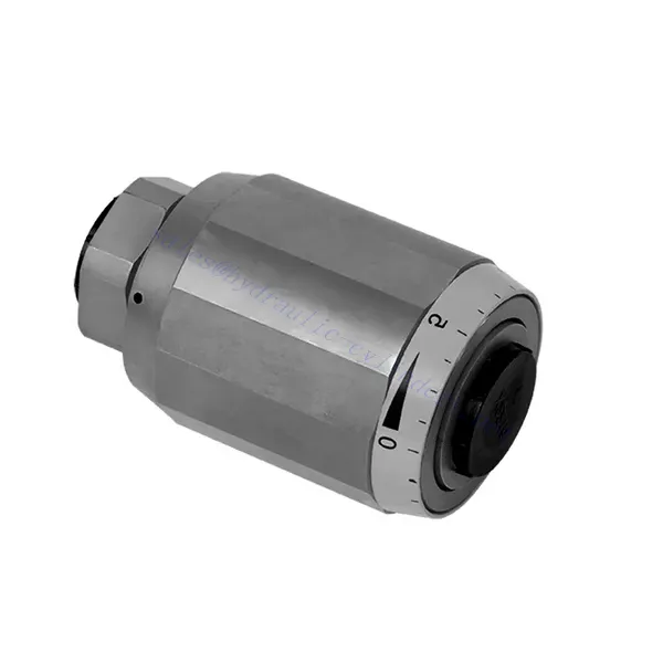
MG/MK Series Throttle And Throttle Check Hydraulic Valve
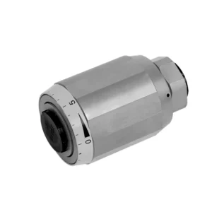

The MG/MK series throttle and throttle check hydraulic valve is a versatile and high-performance hydraulic component designed to optimize control and efficiency in hydraulic systems. With its unique throttle and throttle check functionality, this valve offers precise flow control and ensures the smooth operation of hydraulic actuators.
The MG/MK series throttle and throttle check hydraulic valve is a versatile and reliable solution for precise flow control and enhanced system efficiency. With its throttle functionality, throttle check feature, and customizable flow control options, this valve delivers exceptional performance in various hydraulic applications. Following the recommended usage methods and maintenance guidelines, operators can ensure the longevity, reliability, and optimal functionality of the MG/MK series throttle and check hydraulic valve. Upgrade your hydraulic system with this advanced valve and experience enhanced control, efficiency, and productivity.
MG/MK Series Throttle And Throttle Check Hydraulic Valve Key Characteristics:
- Throttle Functionality:
- The MG/MK series valve features a throttle function that regulates the flow rate of hydraulic fluid.
- It allows for precise control of the fluid flow, enabling fine-tuning of actuator speed and responsiveness.
- Throttle Check Function:
- In addition to throttle control, this valve incorporates a throttle check function.
- The throttle check feature enables the valve to act as a check valve, preventing reverse flow and maintaining system stability.
- Flow Control Versatility:
- The MG/MK Series Valve offers a wide range of flow control options, allowing customization to suit specific application requirements.
- It can be configured for varying flow rates, pressure differentials, and actuator sizes, ensuring compatibility with diverse hydraulic systems.
- Zvýšená účinnost systému:
- By providing precise flow control, the valve minimizes energy loss and optimizes overall system efficiency.
- It allows operators to match the hydraulic flow to the specific load requirements, reducing unnecessary power consumption.
- Spolehlivý výkon:
- The MG/MK Series Valve is built to withstand demanding operating conditions and deliver consistent performance.
- Its robust construction and high-quality materials ensure durability and reliability in various applications.
MG/MK Series Throttle And Throttle Check Hydraulic Valve Parameter:
| Velikost | 6 | 8 | 10 | 15 | 20 | 25 | 30 | |
| Hmotnost | kg | 0.3 | 0.4 | 0.7 | 1.3 | 2.2 | 3.6 | 4.5 |
| Max. operating pressure | bar | 315bar | ||||||
| Cracking pressure for type MK | bar | 0.5 | ||||||
| Max. průtok | l/min | 400 | ||||||
| Rozsah viskozity | mm2/s | 10 až 800 | ||||||
| Rozsah teplot kapaliny | ℃ | -30℃ to +80℃ | ||||||
| Tekutina | Minerální olej; Fosfátový ester | |||||||
| Stupeň kontaminace | Maximální přípustný stupeň znečištění kapaliny: Třída 9. NAS 1638 nebo 20/18/15, ISO4406 | |||||||
MG/MK Series Throttle And Throttle Check Hydraulic Valve Advantages:
• Used in direct tubing installation
• Related to pressure and viscosity
Usage Method Of MG/MK Series Throttle And Throttle Check Hydraulic Valve:
- Vyhodnocení systému:
- Assess the hydraulic system’s requirements, including flow rates, pressure differentials, and actuator specifications.
- Identify the need for throttle and throttle check functionality in the system.
- Výběr ventilu:
- Select the appropriate variant of the MG/MK series valve based on system parameters and desired flow control characteristics.
- Consider factors such as maximum flow rate, pressure rating, and compatibility with other system components.
- Instalace:
- Follow the manufacturer’s installation instructions and ensure proper alignment and connection of the valve.
- Pay attention to flow direction arrows and ensure secure fittings and seals.
- Flow Adjustment:
- Adjust the throttle setting on the valve to achieve the desired flow rate.
- Fine-tune the throttle control to optimize actuator performance and system efficiency.
How Hydraulic Control Valve Works?
A hydraulic control valve is a critical component in hydraulic systems that regulates the flow and pressure of hydraulic fluid. It serves as a control mechanism for directing fluid to different hydraulic actuators and controlling the speed and direction of their movement. The operation of a hydraulic control valve can be described as follows:
- Struktura ventilu:
- A hydraulic control valve comprises a valve body that houses various internal components, such as spools, poppets, or discs.
- The valve body contains ports, passages, and chambers that facilitate the flow of hydraulic fluid.
- Pozice ventilů:
- Hydraulic control valves typically have multiple positions, including open, closed, and partially open.
- V uzavřené poloze ventil zcela blokuje průtok kapaliny.
- In the open position, the valve allows fluid to flow freely through specific ports.
- V částečně otevřené poloze ventil omezuje nebo reguluje průtok kapaliny.
- Funkce šoupátkového ventilu:
- Spool valves are commonly used in hydraulic control systems. They consist of a cylindrical spool with lands or channels.
- The spool is positioned within the valve body and can be moved longitudinally.
- By shifting the spool, different lands align with specific ports, enabling or blocking fluid flow to different actuators.
- The movement of the spool is typically achieved using mechanical linkages, solenoids, or hydraulic pressure acting on the spool.
- Funkce talířového ventilu:
- Poppet valves are another type of hydraulic control valve. They use a movable poppet or disc to control fluid flow.
- Když je talířový ventil v uzavřené poloze, opírá se o sedlo a blokuje průtok kapaliny.
- Pro otevření ventilu se kuželka posune směrem od sedla, což umožní průtok kapaliny skrz otvor.
- The movement of the poppet can be achieved through mechanical linkages or hydraulic pressure.
- Kontrolní mechanismy:
- Hydraulic control valves can be operated manually, mechanically, or through electrical means.
- Manual control involves the use of levers, knobs, or handles to position the valve element.
- Mechanické ovládání využívá mechanické spoje nebo pohony k pohybu ventilového prvku.
- Elektrické ovládání využívá solenoidy nebo jiná elektricky ovládaná zařízení k posunu ventilového prvku.
- Ovládání pohonu:
- Hydraulic control valves direct fluid to various hydraulic actuators, such as cylinders or motors.
- By controlling the valve positions, the hydraulic system can regulate the speed, direction, and force of the actuators.
- For example, adjusting the valve position can control the extension or retraction of a hydraulic cylinder.
- Stabilita a bezpečnost systému:
- Hydraulic control valves play a crucial role in maintaining system stability and safety.
- Pressure relief valves are often incorporated into hydraulic control systems to protect against overpressure.
- These relief valves divert excess fluid to a low-pressure outlet, preventing damage to the system.
Schopnosti a kapacita továrny:
(1) Montáž
Disponujeme prvotřídní nezávislou výzkumnou a vývojovou montážní platformou. Dílna na výrobu hydraulických válců má čtyři poloautomatické montážní linky pro zvedací válce a jednu automatickou montážní linku pro naklápěcí válce s projektovanou roční výrobní kapacitou 1 milion kusů. Dílna na speciální válce je vybavena poloautomatickým čisticím montážním systémem s různými specifikacemi a projektovanou roční výrobní kapacitou 200 000 kusů a je vybavena známým CNC obráběcím zařízením, obráběcím centrem, vysoce přesným speciálním zařízením pro zpracování válců, robotickým svařovacím strojem, automatickým čisticím strojem, automatickým montážním strojem pro válce a automatickou lakovací výrobní linkou. Stávající kritické vybavení má více než 300 sad. Optimální alokace a efektivní využití zdrojů zařízení zajišťuje požadavky na přesnost výrobků a splňuje požadavky na vysokou kvalitu výrobků.


(2) Obrábění
Obrobna je vybavena zakázkovým soustružnickým centrem pro šikmé kolejnice, obráběcím centrem, vysokorychlostním honovacím strojem, svařovacím robotem a dalším souvisejícím zařízením, které zvládne obrábění válcových trubek s maximálním vnitřním průměrem 400 mm a maximální délkou 6 metrů.


(3) Svařování


(4) Lakování a nátěry
S malými a středními válcovými automatickými linkami na nanášení barev na vodní bázi, pro dosažení automatického robotického nakládání a vykládání a automatického stříkání, je konstrukční kapacita 4000 kusů za směnu;
Máme také poloautomatickou linku na výrobu barev pro velké tlakové lahve poháněné řetězem s konstrukční kapacitou 60 lahví za směnu.


(5) Testování
Disponujeme prvotřídními inspekčními zařízeními a zkušebními laboratořemi, abychom zajistili, že výkon válce splňuje požadavky.


Jsme jedním z nejlepších výrobců hydraulických válců. Nabízíme komplexní hydraulické válce. Dodáváme také odpovídající zemědělské převodovkyNaše výrobky jsme exportovali klientům po celém světě a díky vynikající kvalitě výrobků a poprodejnímu servisu jsme si získali dobrou pověst. Vítáme zákazníky doma i v zahraničí, kteří nás kontaktují za účelem vyjednávání obchodních příležitostí, výměny informací a spolupracujte s námi!