
Hydraulické směrové ventily řady WEH s pilotním ovládáním
Hydraulické směrové ventily řady WEH s pilotním ovládáním
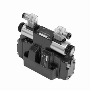
Hydraulické směrové ventily řady WEH s pilotním ovládáním jsou pokročilé komponenty, které poskytují přesné a efektivní ovládání hydraulických systémů. Tyto ventily, navržené tak, aby splňovaly požadavky různých průmyslových odvětví, nabízejí výjimečný výkon, spolehlivost a všestrannost.
Hydraulické směrové ventily řady WEH s pilotním ovládáním jsou spolehlivé a vysoce výkonné komponenty, které obsluze umožňují přesné ovládání a efektivní řízení kapalin v hydraulických systémech. Díky pilotnímu ovládání, výjimečnému směrovému ovládání, široké škále konfigurací a vysokému průtoku nabízejí tyto ventily spolehlivost a všestrannost vyžadovanou v různých odvětvích. Při dodržování doporučených metod používání a pravidelných postupů údržby budou ventily řady WEH i nadále poskytovat výjimečný výkon. Vylepšete svůj hydraulický systém pomocí hydraulických směrových ventilů řady WEH a využijte výhod přesnosti, ovládání a spolehlivosti.
Klíčové vlastnosti hydraulických rozváděčů řady WEH s pilotním ovládáním:
- Pilotně ovládaná konstrukce:
- Ventily řady WEH využívají pilotně ovládanou konstrukci, která zvyšuje jejich citlivost a přesnost regulace.
- Tato konstrukce umožňuje ventilům zvládat vysokotlaké aplikace a snadno zajišťuje optimální výkon.
- Směrové řízení:
- Tyto hydraulické ventily vynikají v přesném řízení směru hydraulické kapaliny.
- Operátoři mohou snadno řídit tok kapaliny a směrovat ji k různým aktuátorům nebo komponentám v hydraulickém systému.
- Široká škála konfigurací:
- Ventily řady WEH jsou k dispozici v různých konfiguracích, včetně různých velikostí, průtoků a jmenovitých tlaků.
- Tato všestrannost umožňuje jejich přizpůsobení specifickým požadavkům aplikace a systémovým specifikacím.
- Vysoká průtoková kapacita:
- Tyto ventily jsou navrženy pro vysoké průtoky, takže jsou vhodné pro aplikace, které vyžadují značný průtok kapaliny.
- Jejich optimalizované vnitřní průchody a robustní konstrukce zajišťují minimální pokles tlaku a efektivní hospodaření s kapalinami.
Hydraulické směrové ventily řady WEH s pilotním ovládáním Parametr:
NG10
| Specifikace | Typ WEH10 | |||||||||
| Max. provozní tlak: P, A, B | 350 | |||||||||
| Přístav T | S externí vypouštěcí lištou pilotního oleje | 315 | ||||||||
| S vnitřní vypouštěcí lištou pilotního oleje | DC 210 AC 160 | |||||||||
| Port Y | S externí vypouštěcí lištou pilotního oleje | DC 210 AC 160 | ||||||||
| Minimální ovládací tlak | S externím přívodem pilotního oleje (neplatí pro C, Z, F, G, H, P, T, V) sloupec |
3-polohový ventil 10 | ||||||||
| Dvoupolohový ventil s vratnou pružinou 10 | ||||||||||
| Dvoupolohový ventil hydraulického zpětného ventilu 7 | ||||||||||
| S interním přívodem pilotního oleje (platí pro C, Z, F) G, H, P, T, V) bar |
6.5 | |||||||||
| Max. ovládací tlak bar | 250 | |||||||||
| Tekutina | Minerální olej, fosfátový ester | |||||||||
| Rozsah teploty kapaliny ℃ | -30 až +80 (těsnění NBR | |||||||||
| -20 až +80 (těsnění FKM) | ||||||||||
| Rozsah viskozity mm2/s | 2,8 až 500 | |||||||||
| Objem spínacího pilotního oleje cm3 | 3-polohový ventil 2.04 | |||||||||
| 2polohový ventil 4.08 | ||||||||||
| Spínací časy (= doba přepnutí ventilu z neutrální polohy do sepnuté polohy) (AC a DC) | ||||||||||
| Ovládací tlak bar | 70 | 140 | 210 | 250 | ||||||
| Klimatizace | DC | Klimatizace | DC | Klimatizace | DC | Klimatizace | DC | |||
| 3-polohový ventil ms | 30 | 65 | 25 | 60 | 20 | 55 | 15 | 50 | ||
| 2polohový ventil ms | 35 | 80 | 30 | 75 | 25 | 70 | 20 | 65 | ||
| Spínací časy (= Doba přepnutí ventilu ze sepnuté polohy do neutrální polohy) | ||||||||||
| 3-polohový ventil ms | 30 | |||||||||
| 2polohový ventil ms | 35 | 40 | 30 | 35 | 25 | 30 | 20 | 25 | ||
| Montážní poloha | Hydraulické zpětné ventily typu HC, HD, HK, HZ, HY jsou instalovány horizontálně, ostatní lze instalovat libovolně. | |||||||||
| Průtok s nejkratší dobou spínání l/min | asi 35 | |||||||||
| Hmotnost | Jednosměrný solenoidový ventil kg | 6.7 | ||||||||
| Dvojitý solenoidový ventil kg | 7.1 | |||||||||
| Regulátor doby spínání kg | 1.0 | |||||||||
| Redukční ventil kg | 0.5 | |||||||||
NG16
| Specifikace | Typ WEH16… | |||||||||||||
| Max. provozní tlak: P, A, B | 350 | |||||||||||||
| Přístav T | S externí vypouštěcí lištou pilotního oleje | 250 | ||||||||||||
| S vnitřní vypouštěcí lištou pilotního oleje | DC 210 AC 160 | |||||||||||||
| Port Y | S externí vypouštěcí lištou pilotního oleje | DC 210 AC 160 | ||||||||||||
| Minimální ovládací tlak | S externím přívodem pilotního oleje (neplatí pro C, Z, F, G, H, P, T, V) bar |
3-polohový ventil 14 | ||||||||||||
| Dvoupolohový ventil s vratnou pružinou 14 | ||||||||||||||
| Dvoupolohový ventil zpětného hydraulického okruhu 14 | ||||||||||||||
| S interním přívodem pilotního oleje (platí pro C, Z, F, G) H, P, T, V) bar |
Při použití předlisování nebo odpovídajícím způsobem velkého průtoku je motor šoupátkového ventilu 4,5 jako C, Z, F, G, H, P, T a V. | |||||||||||||
| Max. ovládací tlak bar | 250 | |||||||||||||
| Tekutina | Minerální olej, fosfátový ester | |||||||||||||
| Rozsah teploty kapaliny ℃ | -30 až +80 (těsnění NBR | |||||||||||||
| -20 až +80 (těsnění FKM) | ||||||||||||||
| Rozsah viskozity mm2/s | 2,8 až 500 | |||||||||||||
| Objem přepínacího pilotního oleje | ||||||||||||||
| – Třípolohový ventil s pružinovým centrováním cm3 | 5.72 | |||||||||||||
| – Dvoupolohový ventil cm3 | 11.45 | |||||||||||||
| * * Spínací časy (= Doba sepnutí ventilu z neutrální polohy do sepnuté polohy) (AC a DC) | ||||||||||||||
| Ovládací tlak bar | 50 | 150 | 250 | |||||||||||
| Klimatizace | DC | Klimatizace | DC | Klimatizace | DC | Klimatizace | DC | Klimatizace | DC | Klimatizace | DC | |||
| – Pružinový středící třípolohový ventil ms | 35 | 65 | 30 | 60 | 30 | 58 | ||||||||
| – 2polohový ventil ms | 45 | 65 | 35 | 55 | 30 | 50 | ||||||||
| **Doby přepnutí (= doba přepnutí ventilu z neutrální polohy do sepnuté polohy)** | ||||||||||||||
| – Pružinový středící třípolohový ventil ms | 30 | |||||||||||||
| – 2polohový ventil ms | 45 | 45 | 35 | 35 | 30 | 30 | ||||||||
| Montážní poloha | Hydraulické zpětné ventily typu C, D, K, Z, Y jsou instalovány horizontálně, ostatní lze instalovat libovolně. | |||||||||||||
| Průtok s nejkratší dobou spínání l/min | asi 35 | |||||||||||||
| Hmotnost v kg | asi 9,5 | |||||||||||||
NG25
| Specifikace | Typ WEH25… | |||||||||||||||||
| Max. provozní tlak: P, A, B | 350 | |||||||||||||||||
| Přístav T | S externí vypouštěcí lištou pilotního oleje | 250 | ||||||||||||||||
| S vnitřní vypouštěcí lištou pilotního oleje | DC 210 AC 160 | |||||||||||||||||
| Port Y | S externí vypouštěcí lištou pilotního oleje | DC 210 AC 160 | ||||||||||||||||
| Minimální ovládací tlak | S externím přívodem pilotního oleje (neplatí pro C, Z, F) G, H, P, T, V) bar |
Pružinový středící třípolohový ventil 13 | ||||||||||||||||
| Dvoupolohový ventil s vratnou pružinou 13 | ||||||||||||||||||
| Dvoupolohový ventil zpětného hydraulického okruhu 8 | ||||||||||||||||||
| S interním přívodem pilotního oleje (platí pro C, Z, F) G, H, P, T, V) bar |
Při použití předlisování nebo odpovídajícím způsobem velkého průtoku je motor šoupátkového ventilu 4,5 jako C, Z, F, G, H, P, T a V. | |||||||||||||||||
| Max. ovládací tlak bar | 250 | |||||||||||||||||
| Tekutina | Minerální olej, fosfátový ester | |||||||||||||||||
| Rozsah teploty kapaliny ℃ | -30 až +80 (těsnění NBR | |||||||||||||||||
| -20 až +80 (těsnění FKM) | ||||||||||||||||||
| Objem přepínacího pilotního oleje | ||||||||||||||||||
| – Třípolohový ventil s pružinovým centrováním cm3 | 14.2 | |||||||||||||||||
| – Dvoupolohový ventil cm3 | 28.4 | |||||||||||||||||
| * Spínací časy (= Doba přepnutí ventilu z neutrální polohy do sepnuté polohy) (AC a DC) | ||||||||||||||||||
| Ovládací tlak bar | 50 | 140 | 210 | 250 | ||||||||||||||
| Klimatizace | DC | Klimatizace | DC | Klimatizace | DC | Klimatizace | DC | |||||||||||
| – Pružinový středící třípolohový ventil ms | 50 | 85 | 40 | 75 | 35 | 70 | 30 | 65 | ||||||||||
| – 2polohový ventil ms | 120 | 160 | 100 | 130 | 85 | 120 | 70 | 105 | ||||||||||
| *Spínací doby (= Doba přepnutí ventilu z neutrální polohy do sepnuté polohy) | ||||||||||||||||||
| – Pružinový středící třípolohový ventil ms | 40 | |||||||||||||||||
| – 2polohový ventil ms | 120 | 125 | 95 | 100 | 85 | 90 | 75 | 80 | ||||||||||
| Montážní poloha | Hydraulické zpětné ventily typu C, D, K, Z, Y jsou instalovány horizontálně, ostatní lze instalovat libovolně. | |||||||||||||||||
| Průtok s nejkratší dobou spínání l/min | asi 35 | |||||||||||||||||
| Hmotnost v kg | asi 18 | |||||||||||||||||
NG32
| Specifikace | Typ WEH32… | |||||||||||||
| Max. provozní tlak: P, A, B | 350 | |||||||||||||
| Přístav T | S externí vypouštěcí lištou pilotního oleje | 250 | ||||||||||||
| S vnitřní vypouštěcí lištou pilotního oleje | DC 210 AC 160 | |||||||||||||
| Port Y | S externí vypouštěcí lištou pilotního oleje | DC 210 AC 160 | ||||||||||||
| Minimální ovládací tlak | S externím přívodem pilotního oleje
S interním přívodem pilotního oleje |
3-polohový ventil 8,5 | ||||||||||||
| Dvoupolohový ventil s vratnou pružinou 10 | ||||||||||||||
| Dvoupolohový ventil zpětného hydraulického okruhu 15 | ||||||||||||||
| S interním přívodem pilotního oleje (platí pro C, Z, F) G, H, P, T, V) bar |
Při použití předlisování nebo odpovídajícím způsobem velkého průtoku je motor šoupátkového ventilu 4,5 jako C, Z, F, G, H, P, T a V. | |||||||||||||
| Max. ovládací tlak bar | 250 | |||||||||||||
| Tekutina | Minerální olej, fosfátový ester | |||||||||||||
| Rozsah teploty kapaliny ℃ | -30 až +80 (těsnění NBR | |||||||||||||
| -20 až +80 (těsnění FKM) | ||||||||||||||
| Rozsah viskozity mm2/s | 2,8 až 500 | |||||||||||||
| Objem přepínacího pilotního oleje | ||||||||||||||
| – Třípolohový ventil s pružinovým centrováním cm3 | 29.4 | |||||||||||||
| – Dvoupolohový ventil cm3 | 58.8 | |||||||||||||
| * Spínací časy (= Doba přepnutí ventilu z neutrální polohy do sepnuté polohy) (AC a DC) | ||||||||||||||
| Ovládací tlak bar | 50 | 150 | 250 | |||||||||||
| Klimatizace | DC | Klimatizace | DC | Klimatizace | DC | |||||||||
| – Pružinový středící třípolohový ventil ms | 65 | 80 | 50 | 90 | 35 | 105 | ||||||||
| – 2polohový ventil ms | 100 | 130 | 75 | 100 | 60 | 115 | ||||||||
| *Spínací doby (= Doba přepnutí ventilu z neutrální polohy do sepnuté polohy) | ||||||||||||||
| – Pružinový středící třípolohový ventil ms | (DC: 50, AC: 60) | |||||||||||||
| – 2polohový ventil ms | 115 | 90 | 35 | 70 | 65 | 65 | ||||||||
| Montážní poloha | Hydraulické zpětné ventily typu C, D, K, Z, Y jsou instalovány horizontálně, zbytek lze instalovat libovolně. | |||||||||||||
| Průtok s nejkratší dobou spínání l/min | asi 50 | |||||||||||||
| Hmotnost v kg | asi 36 | |||||||||||||
Výhody hydraulických rozváděčů řady WEH s pilotním ovládáním:
• Elektrohydraulický směrový ventil řídí dráhu oleje ovládáním hlavního šoupátka
• Elektrohydraulické ovládání WEH
• Montážní plocha odpovídá normám DIN 24340 A, ISO 4401 a CETOP-RP 121H. Připojení k montáži na podstavec.
• Mokrý stejnosměrný nebo střídavý solenoid (volitelné)
• S manuálním nouzovým ovládáním
• Elektropneumatické připojení jako jednoduché nebo středové připojení
• Pružinové nebo hydraulické vyrovnání nebo předpětí
Způsob použití směrových hydraulických ventilů řady WEH s pilotním ovládáním:
- Systémová integrace:
- Určete optimální umístění pro instalaci ventilů řady WEH v hydraulickém systému s ohledem na požadovanou dráhu proudění a požadavky na regulaci.
- Zajistěte kompatibilitu se specifikacemi tlaku a průtoku systému.
- Ventily bezpečně namontujte pomocí vhodných konzol nebo montážního příslušenství.
- Nastavení pilotního ovládání:
- Připojte řídicí potrubí pilotního ventilu k určeným portům na ventilech podle pokynů výrobce.
- Zajistěte správné dimenzování a směrování pilotních vedení pro zachování optimální integrity řídicího signálu.
- Připojení kapalin:
- Pro bezpečné a bezproblémové spojení vyberte kompatibilní hydraulické armatury a hadice.
- Během instalace dodržujte pokyny výrobce ohledně správných hodnot utahovacího momentu.
- Pro zajištění spolehlivého utěsnění použijte vhodné těsnicí materiály na závity nebo pásku.
- Ovládání a nastavení:
- Pro ovládání ventilů řady WEH použijte doporučený způsob ovládání, například ruční páky nebo elektrické ovládání.
- Upravte nastavení ventilů tak, abyste dosáhli požadovaného směru a rychlosti průtoku a zajistili tak optimální výkon.
Jak fungují hydraulické zvedáky ventilů?
Hydraulické zdvihátka ventilů, známé také jako hydraulická zdvihátka nebo hydraulické seřizovače vůle, hrají zásadní roli ve správném provozu spalovacího motoru. Jsou zodpovědné za udržování správné vůle mezi vačkovým hřídelem motoru a komponenty ventilového rozvodu. Zde je přehled fungování hydraulických zdvihátek ventilů:
- Struktura:
- Hydraulické zdvihátka ventilů jsou malá válcová zařízení, obvykle vyrobená z kovu.
- Nacházejí se mezi vačkovým hřídelem a součástmi ventilového rozvodu motoru, jako jsou tlačné tyče, vahadla nebo zdvihátka vačkového hřídele.
- Hydraulický provoz:
- Uvnitř hydraulického zdvihátka ventilu pracuje malý pístový mechanismus na základě hydraulického tlaku.
- Zvedák je naplněn hydraulickou kapalinou, obvykle motorovým olejem, která slouží jako pracovní kapalina.
- Interakce vačkového hřídele:
- Vačkový hřídel má výstupky nebo excentrické tvary, které při otáčení tlačí na zvedáky.
- Jakmile se vačkový hřídel dostane do kontaktu se zvedákem, vyvine sílu, která stlačí jeho vnitřní píst.
- Úprava řas:
- Když je píst zvedáku stlačen, vytlačí hydraulickou kapalinu ze zvedáku malým otvorem.
- Tato hydraulická kapalina je vytlačována do olejových kanálů neboli průchodů motoru.
- Kompenzace řas:
- Vytlačená hydraulická kapalina vytváří hydraulický polštář neboli „pružinový“ efekt, který kompenzuje jakoukoli vůli neboli mezeru mezi lamelou vačkového hřídele a součástmi ventilového rozvodu.
- Tato kompenzace eliminuje nadměrnou vůli a zajišťuje, že ventilový rozvod zůstává v neustálém kontaktu s výstupky vačkového hřídele.
- Péče o řasy:
- Pokud je v rozvodovém rozvodu nadměrná vůle nebo mezera v důsledku opotřebení nebo jiných faktorů, vnitřní píst zvedáku se dále vysune, aby udržel potřebný hydraulický tlak.
- Tato prodloužená poloha umožňuje zvedáku zaujmout dodatečnou vůli, a tím udržet správnou vůli ventilů.
- Tlak oleje a mazání:
- Hydraulické zdvihátka ventilů se pro správnou funkci spoléhají na tlak oleje v motoru.
- Olejové čerpadlo cirkuluje olej motorem a zvedáky jsou nepřetržitě zásobovány olejem pro udržení hydraulického tlaku a mazání.
Schopnosti a kapacita továrny:
(1) Montáž
Disponujeme prvotřídní nezávislou výzkumnou a vývojovou montážní platformou. Dílna na výrobu hydraulických válců má čtyři poloautomatické montážní linky pro zvedací válce a jednu automatickou montážní linku pro naklápěcí válce s projektovanou roční výrobní kapacitou 1 milion kusů. Dílna na speciální válce je vybavena poloautomatickým čisticím montážním systémem s různými specifikacemi a projektovanou roční výrobní kapacitou 200 000 kusů a je vybavena známým CNC obráběcím zařízením, obráběcím centrem, vysoce přesným speciálním zařízením pro zpracování válců, robotickým svařovacím strojem, automatickým čisticím strojem, automatickým montážním strojem pro válce a automatickou lakovací výrobní linkou. Stávající kritické vybavení má více než 300 sad. Optimální alokace a efektivní využití zdrojů zařízení zajišťuje požadavky na přesnost výrobků a splňuje požadavky na vysokou kvalitu výrobků.


(2) Obrábění
Obrobna je vybavena zakázkovým soustružnickým centrem pro šikmé kolejnice, obráběcím centrem, vysokorychlostním honovacím strojem, svařovacím robotem a dalším souvisejícím zařízením, které zvládne obrábění válcových trubek s maximálním vnitřním průměrem 400 mm a maximální délkou 6 metrů.

(3) Svařování

(4) Lakování a nátěry
S malými a středními válcovými automatickými linkami na nanášení barev na vodní bázi, pro dosažení automatického robotického nakládání a vykládání a automatického stříkání, je konstrukční kapacita 4000 kusů za směnu;
Máme také poloautomatickou linku na výrobu barev pro velké tlakové lahve poháněné řetězem s konstrukční kapacitou 60 lahví za směnu.


(5) Testování
Disponujeme prvotřídními inspekčními zařízeními a zkušebními laboratořemi, abychom zajistili, že výkon válce splňuje požadavky.

Jsme jedním z nejlepších výrobců hydraulických válců. Nabízíme komplexní hydraulické válce. Dodáváme také odpovídající zemědělské převodovkyNaše výrobky jsme exportovali klientům po celém světě a díky vynikající kvalitě výrobků a poprodejnímu servisu jsme si získali dobrou pověst. Vítáme zákazníky doma i v zahraničí, kteří nás kontaktují za účelem vyjednávání obchodních příležitostí, výměny informací a spolupracujte s námi!


