


Hydraulický směrový ventil řady WMM s mechanickým, ručním ovládáním
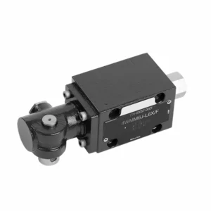

Hydraulický směrový ventil řady WMM s mechanickým ručním ovládáním je všestranné a spolehlivé řešení určené pro přesné řízení hydraulických systémů. Tento hydraulický ventil nabízí zvýšenou účinnost a flexibilitu díky svým pokročilým funkcím a robustní konstrukci.
Hydraulický směrový ventil řady WMM s mechanickým ručním ovládáním je spolehlivým a všestranným řešením pro hydraulické systémy. Jeho automatický ruční provoz a přesné směrové řízení nabízejí zvýšenou flexibilitu a kontrolu pro různé aplikace. Při dodržování doporučených metod používání a pravidelných postupů údržby bude hydraulický ventil řady WMM i nadále poskytovat efektivní a spolehlivý provoz. Vylepšete svůj hydraulický systém směrovým ventilem řady WMM a využijte výhod vylepšené kontroly a všestrannosti.
Hydraulický směrový ventil řady WMM s mechanickým a ručním ovládáním, klíčové vlastnosti:
- Mechanické, ruční ovládání:
- Hydraulický ventil řady WMM se vyznačuje mechanickým, ručním ovládáním, které umožňuje obsluze ručně ovládat polohu ventilu.
- To poskytuje flexibilitu a kontrolu v aplikacích, kde je žádoucí nebo vyžadované ruční ovládání.
- Směrové řízení:
- Tento hydraulický ventil umožňuje přesné řízení směru průtoku kapaliny v hydraulickém systému.
- Umožňuje operátorům zvolit požadovanou dráhu proudění, což zajišťuje efektivní a spolehlivý provoz.
- Odolná konstrukce:
- Hydraulický ventil řady WMM je vyroben z vysoce kvalitních materiálů, což zaručuje odolnost a dlouhou životnost.
- Jeho robustní konstrukce vydrží náročné provozní podmínky a poskytuje spolehlivý výkon.
- Kompaktní velikost:
- The valve’s compact size allows easy integration into hydraulic systems with limited space.
- Je ideální pro aplikace s omezeným prostorem, aniž by to ohrozilo výkon.
Směrový hydraulický ventil řady WMM s mechanickým, ručním ovládáním Parametr:
NG6
| Rozsah teplot kapaliny | ℃ | -30 až +80 (těsnění NBR) | |
| -20 až +80 (těsnění FKM) | |||
| Port Max. provozní tlak | Přístav ABP | bar | 315 |
| Přístav T | bar | 160 | |
| Max. průtok | l/min | 60 | |
| Průtoková plocha (spínací neutrální poloha) | Typ Q | mm2 | Pro symbol Q, 6% jmenovitého průřezu |
| Typ W | mm2 | Pro symbol W, 3% jmenovitého průřezu | |
| Tekutina | Minerální olej; Fosfátový ester | ||
| Rozsah viskozity | mm2/s | 2,8 až 500 | |
| Stupeň kontaminace | Maximální přípustný stupeň znečištění kapaliny: Třída 9. NAS 1638 nebo 20/18/15, ISO4406 | ||
| Hmotnost | kg | 1.6 | |
NG10
| Rozsah teplot kapaliny | ℃ | -30 až +80 (těsnění NBR) | |
| -20 až +80 (těsnění FKM) | |||
| Port Max. provozní tlak | Přístav ABP | bar | 315 |
| Přístav T | bar | 160 | |
| Max. průtok | l/min | 120 | |
| Průřez proudění (spínací neutrální poloha) | Typ V | mm2 | 11(A/B → T); 10,3(P → A/B) |
| Typ W | mm2 | 2,5 (A/B → T) | |
| Typ Q | mm2 | 5,5 (A/B → T) | |
| Tekutina | Minerální olej; Fosfátový ester | ||
| Rozsah viskozity | mm2/s | 2,8 až 500 | |
| Stupeň kontaminace | Maximální přípustný stupeň znečištění kapaliny: Třída 9. NAS 1638 nebo 20/18/15, ISO4406 | ||
| Hmotnost | kg | 4.4 | |
NG16-32
| NS | 16 | 25 | 32 |
| Hmotnost | asi 8 | asi 12,2 | asi 49 |
| Ovládací síla s aretací N | asi 75 | asi 105 | asi 170 |
| s vratnou pružinou N | |||
| Úhel ovládání kolem neutrální polohy | 2*26° | 2*32° | 2*30° |
| Max. provozní tlak Port A, B, P bar | 315 | ||
| Port T bar | 250 | ||
| Tekutina | Minerální olej vhodný pro těsnění NBR a FKM | ||
| Phosphate ester – for FKM seal | |||
| Rozsah teplot kapaliny | -30 až +80 (těsnění NBR) | ||
| -20 až +80 (těsnění FKM) | |||
| Rozsah viskozity mm2/s | 2,8 až 380 | ||
| Stupeň kontaminace | Maximální přípustný stupeň znečištění kapaliny: Třída 9. NAS 1638 nebo 20/18/15, ISO4406 | ||
Hydraulický směrový ventil řady WMM s mechanickým, manuálním ovládáním Výhody:
• Přímočinný rozváděč přímočinný rozváděč
• Montáž na podkladovou desku
• Ovládání rukojetí
• Montážní plocha odpovídá normám DIN 24340 A, ISO 4401
Způsob použití směrového hydraulického ventilu řady WMM s mechanickým, ručním ovládáním:
- Systémová integrace:
- Určete vhodné umístění hydraulického ventilu řady WMM v hydraulickém systému s ohledem na požadovaný směr průtoku a požadavky na řízení.
- Ensure compatibility with the system’s pressure and flow specifications.
- Ventil bezpečně namontujte pomocí vhodných konzol nebo montážního příslušenství.
- Připojení kapalin:
- Pro bezpečné a bezproblémové spojení vyberte kompatibilní hydraulické armatury a hadice.
- Follow the manufacturer’s instructions for proper torque values during the installation process.
- Pro zajištění spolehlivého utěsnění použijte vhodné těsnicí materiály na závity nebo pásku.
- Ruční provoz:
- Seznamte se s mechanismem ručního ovládání ventilu, včetně páky nebo knoflíku používaného k ovládání polohy hydraulického ventilu.
- Ujistěte se, že obsluha rozumí správnému postupu pro ruční nastavení polohy ventilu.
- Kalibrace systému:
- Kalibrujte polohu a pohyb hydraulického ventilu podle požadovaného směru průtoku a požadavků na regulaci.
- Ručně seřiďte ventil, abyste dosáhli požadované dráhy proudění a zajistili jeho správnou funkci.
Jak seřídit ventily na hydraulické kladkové vačce?
Adjusting valves on a hydraulic roller cam requires careful attention to detail and following the proper procedure. Here’s a step-by-step guide to help you adjust the valves correctly:
- Připravte motor:
- Před zahájením seřizování se ujistěte, že je motor vypnutý a studený na dotek.
- Vyhledejte kryty ventilů a sejměte je, abyste získali přístup k součástem ventilového rozvodu.
- Určete správnou sekvenci seřízení ventilů:
- Consult the engine manufacturer’s specifications or service manual to determine the correct valve adjustment sequence for your specific engine.
- Určení polohy horní úvrati (TDC):
- Rotate the engine’s crankshaft in the normal direction of rotation until the number one piston reaches the top dead center position on its compression stroke.
- Pro přesnou identifikaci polohy horní úvrati použijte časovou značku na vyvažovači harmonických kmitů nebo setrvačníku a časovací ukazatel.
- Nastavení vůle ventilu:
- Začněte s prvním válcem v sekvenci seřízení ventilů.
- Povolte pojistnou matici na čepu vahadla pomocí vhodného klíče nebo objímky.
- Pro kontrolu vůle ventilu mezi vahadlem a dříkem ventilu použijte spárovou měrku o doporučené tloušťce specifikované výrobcem motoru.
- Vsuňte spárovou měrku mezi vahadlo a dřík ventilu. Měli byste cítit mírný odpor, ale stále byste měli být schopni měrkou pohybovat tam a zpět.
- Vůli ventilů seřiďte utahováním nebo povolováním čepu vahadla, dokud nedosáhnete správné vůle. Otáčením čepu ve směru hodinových ručiček se vůle snižuje, otáčením proti směru hodinových ručiček se vůle zvětšuje.
- Once you’ve set the correct valve lash, hold the rocker arm stud in place and tighten the lock nut securely.
- Opakujte postup:
- Přejděte k dalšímu válci v sekvenci seřízení ventilů a opakujte kroky 4 a 5, dokud nebudou seřízeny všechny ventily.
- Znovu namontujte kryty ventilů:
- Once you’ve completed the valve adjustment on all cylinders, reinstall the valve covers and ensure they are properly sealed to prevent oil leaks.
- Dvojitá kontrola:
- After adjusting the valves, it’s a good practice to go through the entire valve adjustment sequence once more to confirm that all clearances are within the specified range.
Schopnosti a kapacita továrny:
(1) Montáž
Disponujeme prvotřídní nezávislou výzkumnou a vývojovou montážní platformou. Dílna na výrobu hydraulických válců má čtyři poloautomatické montážní linky pro zvedací válce a jednu automatickou montážní linku pro naklápěcí válce s projektovanou roční výrobní kapacitou 1 milion kusů. Dílna na speciální válce je vybavena poloautomatickým čisticím montážním systémem s různými specifikacemi a projektovanou roční výrobní kapacitou 200 000 kusů a je vybavena známým CNC obráběcím zařízením, obráběcím centrem, vysoce přesným speciálním zařízením pro zpracování válců, robotickým svařovacím strojem, automatickým čisticím strojem, automatickým montážním strojem pro válce a automatickou lakovací výrobní linkou. Stávající kritické vybavení má více než 300 sad. Optimální alokace a efektivní využití zdrojů zařízení zajišťuje požadavky na přesnost výrobků a splňuje požadavky na vysokou kvalitu výrobků.


(2) Obrábění
Obrobna je vybavena zakázkovým soustružnickým centrem pro šikmé kolejnice, obráběcím centrem, vysokorychlostním honovacím strojem, svařovacím robotem a dalším souvisejícím zařízením, které zvládne obrábění válcových trubek s maximálním vnitřním průměrem 400 mm a maximální délkou 6 metrů.


(3) Svařování


(4) Lakování a nátěry
S malými a středními válcovými automatickými linkami na nanášení barev na vodní bázi, pro dosažení automatického robotického nakládání a vykládání a automatického stříkání, je konstrukční kapacita 4000 kusů za směnu;
Máme také poloautomatickou linku na výrobu barev pro velké tlakové lahve poháněné řetězem s konstrukční kapacitou 60 lahví za směnu.


(5) Testování
Disponujeme prvotřídními inspekčními zařízeními a zkušebními laboratořemi, abychom zajistili, že výkon válce splňuje požadavky.


Jsme jedním z nejlepších výrobců hydraulických válců. Nabízíme komplexní hydraulické válce. Dodáváme také odpovídající zemědělské převodovkyNaše výrobky jsme exportovali klientům po celém světě a díky vynikající kvalitě výrobků a poprodejnímu servisu jsme si získali dobrou pověst. Vítáme zákazníky doma i v zahraničí, kteří nás kontaktují za účelem vyjednávání obchodních příležitostí, výměny informací a spolupracujte s námi!