Hydraulický směrový ventil řady WMR s mechanickým, ručním ovládáním
Hydraulický směrový ventil řady WMR s mechanickým, ručním ovládáním
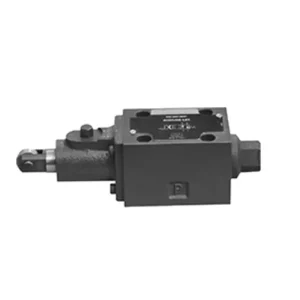
Hydraulický směrový ventil řady WMR s mechanickým ručním ovládáním je špičkovým řešením určeným pro přesné ovládání hydraulických systémů. Díky pokročilým funkcím a robustní konstrukci nabízí tento ventil zvýšenou účinnost a flexibilitu.
Hydraulický směrový ventil řady WMR s mechanickým ručním ovládáním je spolehlivým a všestranným řešením pro hydraulické systémy. Jeho automatický i ruční provoz a přesné směrové řízení nabízejí zvýšenou flexibilitu a kontrolu pro různé aplikace. Při dodržování doporučených metod používání a pravidelných postupů údržby bude ventil řady WMR i nadále poskytovat efektivní a spolehlivý provoz. Vylepšete svůj hydraulický systém směrovým hydraulickým ventilem řady WMR a využijte výhod vylepšené kontroly a všestrannosti.
Hydraulický směrový ventil řady WMR s mechanickým a ručním ovládáním, klíčové vlastnosti:
- Mechanické, ruční ovládání:
- Ventil řady WMR se vyznačuje mechanickým, ručním ovládáním, které umožňuje obsluze ručně ovládat polohu ventilu.
- To poskytuje flexibilitu a kontrolu v aplikacích, kde je žádoucí nebo vyžadované ruční ovládání.
- Směrové řízení:
- Tento hydraulický ventil umožňuje přesné řízení směru průtoku kapaliny v hydraulickém systému.
- Umožňuje operátorům zvolit požadovanou dráhu proudění, což zajišťuje efektivní a spolehlivý provoz.
- Odolná konstrukce:
- Ventil řady WMR je vyroben z vysoce kvalitních materiálů, což zaručuje odolnost a dlouhou životnost.
- Jeho robustní konstrukce vydrží náročné provozní podmínky a poskytuje spolehlivý výkon.
- Široký rozsah použití:
- Ventil řady WMR je vhodný pro různá odvětví a aplikace, včetně výroby, stavebnictví, zemědělství atd.
- Lze jej použít v hydraulických systémech, které vyžadují přesné a efektivní řízení kapaliny.
Hydraulický směrový ventil řady WMR s mechanickým, ručním ovládáním Parametr:
NG6
| Montážní poloha | Volitelný | ||
| Rozsah teplot kapaliny | ℃ | -30 až +80 (těsnění NBR) | |
| -20 až +80 (těsnění FKM) | |||
| Port Max. provozní tlak | Přístav ABP | bar | 315 |
| Přístav T | bar | 60 | |
| Max. průtok | l/min | 60 | |
| Průřez proudění (spínací neutrální poloha) | Typ Q | mm2 | Pro symbol Q, 6% jmenovitého průřezu |
| Typ W | mm2 | Pro symbol W, 3% jmenovitého průřezu | |
| Tekutina | Minerální olej; Fosfátový ester | ||
| Rozsah viskozity | mm2/s | 2,8 až 500 | |
| Stupeň kontaminace | Maximální přípustný stupeň znečištění kapaliny: Třída 9. NAS 1638 nebo 20/18/15, ISO4406 | ||
| Hmotnost | kg | 1.4 | |
NG10
| Montážní poloha | Volitelný | ||
| Rozsah teplot kapaliny | ℃ | -30 až +80 (těsnění NBR) | |
| -20 až +80 (těsnění FKM) | |||
| Port Max. provozní tlak | Přístav ABP | bar | 315 |
| Přístav T | bar | 60 | |
| Max. průtok | l/min | 120 | |
| Průřez proudění (spínací neutrální poloha) | Typ V | mm2 | 11(A/B → T); 10,3(P → A/B) |
| Typ W | mm2 | 2,5 (A/B → T) | |
| Typ Q | mm2 | 5,5 (A/B → T) | |
| Tekutina | Minerální olej; Fosfátový ester | ||
| Rozsah viskozity | mm2/s | 2,8 až 500 | |
| Stupeň kontaminace | Maximální přípustný stupeň znečištění kapaliny: Třída 9. NAS 1638 nebo 20/18/15, ISO4406 | ||
| Hmotnost | kg | 4 | |
Hydraulický směrový ventil řady WMR s mechanickým, manuálním ovládáním Výhody:
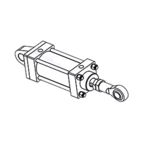
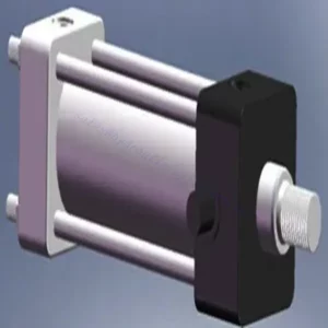
• Přímočinný rozváděč přímočinný rozváděč
• Rolovací kolečko se může otáčet o 90°
• Devatenáct standardních funkcí šoupátkového ventilu
Způsob použití směrového hydraulického ventilu řady WMR s mechanickým, ručním ovládáním:
- Systémová integrace:
- Určete vhodné umístění ventilu řady WMR v hydraulickém systému s ohledem na požadovaný směr průtoku a požadavky na regulaci.
- Zajistěte kompatibilitu se specifikacemi tlaku a průtoku systému.
- Ventil bezpečně namontujte pomocí vhodných konzol nebo montážního příslušenství.
- Připojení kapalin:
- Pro bezpečné a bezproblémové spojení vyberte kompatibilní hydraulické armatury a hadice.
- Během instalace dodržujte pokyny výrobce ohledně správných hodnot utahovacího momentu.
- Pro zajištění spolehlivého utěsnění použijte vhodné těsnicí materiály na závity nebo pásku.
- Ruční provoz:
- Seznamte se s mechanismem ručního ovládání ventilu, včetně páky nebo knoflíku používaného k ovládání polohy ventilu.
- Ujistěte se, že obsluha rozumí správnému postupu pro ruční nastavení polohy ventilu.
- Kalibrace systému:
- Kalibrujte polohu a pohyb ventilu podle požadovaného směru průtoku a požadavků na regulaci.
- Ručně seřiďte ventil, abyste dosáhli požadované dráhy proudění a zajistili jeho správnou funkci.
Jak seřídit hydraulické zdvihátka ventilů?
Seřízení hydraulických zdvihátek ventilů je klíčovým úkolem údržby, který zajišťuje správný výkon motoru a předchází problémům, jako je hluk ventilového rozvodu a snížený výkon. Zde je podrobný návod, jak seřídit hydraulické zdvihátka ventilů:
- Připravte motor:
- Před zahájením procesu seřizování se ujistěte, že je motor vypnutý a studený na dotek.
- Odstraňte všechny součásti potřebné pro přístup k víkům ventilů, jako je sestava čističe vzduchu nebo kabely zapalovacích svíček.
- Určete správnou sekvenci seřízení ventilů:
- Pro určení správného pořadí seřízení ventilů pro váš konkrétní motor se řiďte specifikacemi výrobce motoru nebo servisní příručkou.
- Některé motory mají pořadí zapalování, které určuje danou sekvenci, zatímco jiné mají specifické pokyny založené na číslování válců.
- Určení polohy horní úvrati (TDC):
- Otáčejte klikovým hřídelem motoru v normálním směru otáčení, dokud píst číslo jedna nedosáhne při kompresním zdvihu horní úvrati (TDC).
- Pro přesné určení polohy horní úvrati použijte časovou značku na vyvažovači harmonických kmitů nebo setrvačníku a časovací ukazatel.
- Seřízení zdvihátek ventilů:
- Začněte s prvním válcem v sekvenci seřízení ventilů.
- Pro přístup k vahadlům a zdvihátkům ventilů sejměte víko ventilů.
- Povolte pojistnou matici na vahadle pomocí vhodného klíče nebo objímky.
- Otáčením stavěcího šroubu nebo čepu na vahadle ventilu ve směru hodinových ručiček zmenšíte vůli ventilu, otáčením proti směru hodinových ručiček ji zvětšíte.
- Zkontrolujte doporučenou vůli ventilů podle specifikací výrobce motoru. Pomocí spárové měrky změřte vůli mezi vahadlem a dříkem ventilu.
- Seřizujte zdvihátko ventilu, dokud nedosáhnete správné vůle. Měli byste cítit mírný odpor, ale stále byste měli být schopni pohybovat spárovou měrkou tam a zpět.
- Držte stavěcí šroub nebo čep na místě a pevně utáhněte pojistnou matici.
- Opakujte postup:
- Přejděte k dalšímu válci v pořadí seřízení ventilů a opakujte kroky 4 a 5, dokud nebudou seřízeny všechny zdvihátka ventilů.
- Znovu namontujte kryty ventilů:
- Jakmile dokončíte seřízení ventilů na všech válcích, nainstalujte zpět víka ventilů a ujistěte se, že jsou řádně utěsněna, aby nedošlo k úniku oleje.
- Dvojitá kontrola:
- Po seřízení zdvihátek ventilů je vhodné znovu projít celým postupem seřízení ventilů, abyste se ujistili, že všechny vůle jsou v předepsaném rozsahu.
Schopnosti a kapacita továrny:
(1) Montáž
Disponujeme prvotřídní nezávislou výzkumnou a vývojovou montážní platformou. Dílna na výrobu hydraulických válců má čtyři poloautomatické montážní linky pro zvedací válce a jednu automatickou montážní linku pro naklápěcí válce s projektovanou roční výrobní kapacitou 1 milion kusů. Dílna na speciální válce je vybavena poloautomatickým čisticím montážním systémem s různými specifikacemi a projektovanou roční výrobní kapacitou 200 000 kusů a je vybavena známým CNC obráběcím zařízením, obráběcím centrem, vysoce přesným speciálním zařízením pro zpracování válců, robotickým svařovacím strojem, automatickým čisticím strojem, automatickým montážním strojem pro válce a automatickou lakovací výrobní linkou. Stávající kritické vybavení má více než 300 sad. Optimální alokace a efektivní využití zdrojů zařízení zajišťuje požadavky na přesnost výrobků a splňuje požadavky na vysokou kvalitu výrobků.


(2) Obrábění
Obrobna je vybavena zakázkovým soustružnickým centrem pro šikmé kolejnice, obráběcím centrem, vysokorychlostním honovacím strojem, svařovacím robotem a dalším souvisejícím zařízením, které zvládne obrábění válcových trubek s maximálním vnitřním průměrem 400 mm a maximální délkou 6 metrů.

(3) Svařování

(4) Lakování a nátěry
S malými a středními válcovými automatickými linkami na nanášení barev na vodní bázi, pro dosažení automatického robotického nakládání a vykládání a automatického stříkání, je konstrukční kapacita 4000 kusů za směnu;
Máme také poloautomatickou linku na výrobu barev pro velké tlakové lahve poháněné řetězem s konstrukční kapacitou 60 lahví za směnu.


(5) Testování
Disponujeme prvotřídními inspekčními zařízeními a zkušebními laboratořemi, abychom zajistili, že výkon válce splňuje požadavky.

Jsme jedním z nejlepších výrobců hydraulických válců. Nabízíme komplexní hydraulické válce. Dodáváme také odpovídající zemědělské převodovkyNaše výrobky jsme exportovali klientům po celém světě a díky vynikající kvalitě výrobků a poprodejnímu servisu jsme si získali dobrou pověst. Vítáme zákazníky doma i v zahraničí, kteří nás kontaktují za účelem vyjednávání obchodních příležitostí, výměny informací a spolupracujte s námi!