ZDR-serien direkte betjent trykreducerende hydraulisk ventil
ZDR-serien direkte betjent trykreducerende hydraulisk ventil
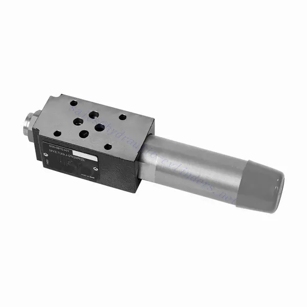
The ZDR series direct-operated pressure-reducing hydraulic valve is a highly efficient and reliable component that provides accurate pressure control in hydraulic systems. With its direct-operated design and exceptional performance, this valve ensures precise pressure reduction to meet specific system requirements.
The ZDR series direct-operated pressure-reducing hydraulic valve is a high-performance solution for precise pressure control in hydraulic systems. With its direct-operated design, accurate pressure control, wide pressure range, and high flow capacity, this valve ensures efficient and reliable pressure reduction while protecting system components. By following the recommended usage methods and maintenance practices, the ZDR series valve delivers reliable performance, extending the lifespan of hydraulic systems. Upgrade your hydraulic system with the ZDR series direct-operated pressure-reducing hydraulic valve and experience optimal pressure control for enhanced system efficiency and productivity.
ZDR Series Direct Operated Pressure Reducing Hydraulic Valve Key Characteristics:
- Direct-Operated Design:
- The ZDR series valve features a direct-operated design, which enables it to provide precise pressure control without the need for external pilot circuits.
- This design simplifies installation and reduces complexity in hydraulic systems.
- Accurate Pressure Control:
- This valve offers exceptional accuracy in pressure control, allowing hydraulic systems to maintain the desired pressure range with high reliability.
- It ensures stable operation and protects sensitive system components from excessive pressure.
- Wide Pressure Range:
- The ZDR series valve is available in various pressure ranges, making it suitable for diverse hydraulic applications.
- The flexibility in pressure range allows customization to match specific system requirements and optimize performance.
- Høj flowkapacitet:
- This valve exhibits excellent flow capacity, enabling it to handle high flow rates while maintaining precise pressure control.
- It ensures efficient fluid regulation and uninterrupted system operation, even in demanding applications.
ZDR Series Direct Operated Pressure Reducing Hydraulic Valve Parameter:
| Specifikationer | NG10 | NG16 | ||
| Væske | Mineralolie egnet til NBR- og FKM-tætninger | |||
| Fosfatester til FKM-tætning | ||||
| Væsketemperaturområde | ℃ | -30 til +80 (NBR-tætninger) | ||
| -20 til +80 (FKM-tætninger) | ||||
| Viskositetsområde | mm2/s | 10 til 800 | ||
| Grad af forurening | Maksimal tilladt grad af væskeforurening: Klasse 9. NAS 1638 eller 20/18/15, ISO4406 | |||
| Nominal pressure | bar | 315 | ||
| Maks. driftstryk | Havn P | bar | 315 | |
| Maks. driftstryk | Havn A | bar | 315 | 250 |
| Maks. driftstryk | Port Y | bar | Separat og ved nultryk til tanken | |
| Indstilling af tryk | Min. | bar | Dependent on the flow (see curves) | |
| Max. | bar | 50; 100; 200; 315 | 50; 100; 200; 250 | |
| Maks. flowhastighed | l/min | 120 | 220 | |
| Vægt | kg | about 6.5 | about 8.8 | |
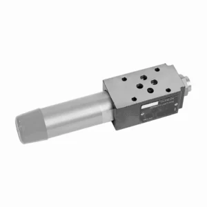
ZDR Series Direct Operated Pressure Reducing Hydraulic Valve Advantages:
• Sandwich-lignende struktur
• Installationsfladen følger DIN 24340 A og ISO 4401
• Fire trykområder
• To justeringstyper: knap, justeringsskrue med beskyttelseshætte
• With pressure gauge interface
• Optional one directional valve
Usage Method Of ZDR Series Direct Operated Pressure Reducing Hydraulic Valve:
- Systemanalyse:
- Conduct a thorough hydraulic system analysis to determine the specific pressure control requirements.
- Consider maximum operating pressure, desired pressure range, and flow rates.
- Valg af ventil:
- Select the appropriate ZDR series valve variant based on the system’s pressure control specifications.
- Overvej trykklassificering, flowkapacitet og kompatibilitet med andre systemkomponenter.
- Installation:
- Follow the manufacturer’s instructions to correctly install the ZDR series direct-operated pressure-reducing valve in the hydraulic system.
- Sørg for korrekt justering og sikre forbindelser for at forhindre lækager og optimere ydeevnen.
- Kalibrering:
- Calibrate the valve to set the desired downstream pressure.
- Utilize pressure gauges or other measurement devices to adjust the valve for optimal pressure control accurately.
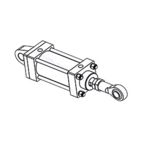
How Does A Hydraulic Selector Valve Work?
A hydraulic selector valve, also known as a hydraulic diverter valve or hydraulic control valve, is a device used to direct the flow of hydraulic fluid in a hydraulic system. It allows the operator to control the path of fluid flow by selecting different hydraulic circuits or components to operate. Here’s a breakdown of how a hydraulic selector valve works:
- Ventilkonstruktion:
- A hydraulic selector valve consists of a body with multiple ports and internal passages.
- It typically has an actuating mechanism, such as a lever or a solenoid, to control the movement of the valve spool or poppet.
- Port Configuration:
- A selector valve has multiple ports, usually labeled as A, B, and C, or sometimes referred to as P, T, and A/B/C.
- Port P (Pressure) connects to the hydraulic pump or the high-pressure side of the system.
- Port T (Tank) connects to the hydraulic reservoir or the low-pressure side of the system.
- Ports A, B, and C are the output ports that connect to different hydraulic circuits or components.
- Ventilpositioner:
- The selector valve has different positions that determine the flow path of the hydraulic fluid.
- Common positions include “A,” “B,” “C,” “AB,” “AC,” and “BC,” depending on the specific valve design.
- Fluid Flow Control:
- When the valve is in the neutral or default position, typically labeled “N,” the fluid flow is blocked, and no flow occurs between any of the ports.
- When the operator actuates the valve by moving the lever or energizing the solenoid, the valve spool or poppet shifts to a different position, enabling fluid flow.
- Flow Path Selection:
- By moving the actuating mechanism, the operator can select the desired flow path.
- For example, when the valve is in position “A,” fluid flows from port P to port A, allowing the hydraulic circuit or component connected to port A to operate.
- Multiple Flow Paths:
- Depending on the specific valve design, a hydraulic selector valve can provide multiple flow paths.
- For instance, in position “AB,” fluid can flow from port P to both ports A and B simultaneously, allowing operation of two separate hydraulic circuits or components.
- Kontrol og drift:
- The actuating mechanism of the selector valve can be manual, where the operator physically moves a lever or knob, or it can be electric or pneumatic, using solenoids or other control devices.
- Electrically controlled selector valves can be integrated into automated systems or controlled remotely.
- System Flexibility:
- Hydraulic selector valves provide flexibility in system design and operation.
- They allow the operator to switch between different hydraulic circuits or components, facilitating tasks such as equipment positioning, attachment control, or switching between different implements.
Fabrikkens kapacitet og kapacitet:
(1) Samling
Vi har en førsteklasses uafhængig forsknings- og udviklingsplatform til montering. Værkstedet for produktion af hydrauliske cylindre har fire halvautomatiske løftecylindermonteringslinjer og en automatisk vippecylindermonteringslinje med en designmæssig årlig produktionskapacitet på 1 million enheder. Det specielle cylinderværksted er udstyret med forskellige specifikationer for et halvautomatisk rengøringsmonteringssystem med en designmæssig årlig produktionskapacitet på 200.000 og udstyret med berømt CNC-bearbejdningsudstyr, et bearbejdningscenter, et specialudstyr til højpræcisionscylinderbearbejdning, en robotsvejsemaskine, en automatisk rengøringsmaskine, en automatisk cylindermonteringsmaskine og en automatisk malingslinje. Eksisterende kritisk udstyr på mere end 300 sæt (sæt). Optimal allokering og effektiv udnyttelse af udstyrsressourcer sikrer produkternes nøjagtighedskrav og opfylder produkternes høje kvalitetsbehov.


(2) Maskinbearbejdning
Bearbejdningsværkstedet er udstyret med et specialfremstillet drejecenter til skrå skinner, bearbejdningscenter, højhastigheds-honemaskine, svejserobot og andet relateret udstyr, der kan håndtere bearbejdning af cylinderrør med en maksimal indre diameter på 400 mm og en maksimal længde på 6 meter.

(3) Svejsning

(4) Maling og overfladebehandling
Med små og mellemstore cylindriske automatiske vandbaserede malingsbelægningslinjer, for at opnå automatisk robotpåfyldning og -aflæsning samt automatisk sprøjtning, er den designmæssige kapacitet på 4000 stykker pr. skift;
Vi har også en halvautomatisk malingsproduktionslinje til store cylindre drevet af en kabelkæde med en designkapacitet på 60 kasser pr. skift.


(5) Testning
Vi har førsteklasses inspektionsfaciliteter og testbænke for at sikre, at cylinderens ydeevne opfylder kravene.

Vi er en af de bedste producenter af hydrauliske cylindre. Vi kan tilbyde et omfattende udvalg af hydrauliske cylindre. Vi leverer også tilsvarende landbrugsgearkasserVi har eksporteret vores produkter til kunder over hele verden og har opnået et godt omdømme på grund af vores overlegne produktkvalitet og eftersalgsservice. Vi byder kunder i ind- og udland velkommen til at kontakte os for at forhandle forretninger, udveksle information og samarbejde med os!