


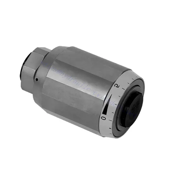
MG/MK-serien gasspjæld og gasspjældskontrol hydraulisk ventil
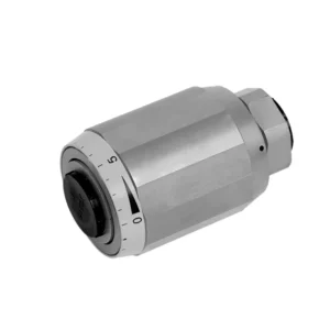

The MG/MK series throttle and throttle check hydraulic valve is a versatile and high-performance hydraulic component designed to optimize control and efficiency in hydraulic systems. With its unique throttle and throttle check functionality, this valve offers precise flow control and ensures the smooth operation of hydraulic actuators.
The MG/MK series throttle and throttle check hydraulic valve is a versatile and reliable solution for precise flow control and enhanced system efficiency. With its throttle functionality, throttle check feature, and customizable flow control options, this valve delivers exceptional performance in various hydraulic applications. Following the recommended usage methods and maintenance guidelines, operators can ensure the longevity, reliability, and optimal functionality of the MG/MK series throttle and check hydraulic valve. Upgrade your hydraulic system with this advanced valve and experience enhanced control, efficiency, and productivity.
MG/MK Series Throttle And Throttle Check Hydraulic Valve Key Characteristics:
- Throttle Functionality:
- The MG/MK series valve features a throttle function that regulates the flow rate of hydraulic fluid.
- It allows for precise control of the fluid flow, enabling fine-tuning of actuator speed and responsiveness.
- Throttle Check Function:
- In addition to throttle control, this valve incorporates a throttle check function.
- The throttle check feature enables the valve to act as a check valve, preventing reverse flow and maintaining system stability.
- Flow Control Versatility:
- The MG/MK Series Valve offers a wide range of flow control options, allowing customization to suit specific application requirements.
- It can be configured for varying flow rates, pressure differentials, and actuator sizes, ensuring compatibility with diverse hydraulic systems.
- Forbedret systemeffektivitet:
- By providing precise flow control, the valve minimizes energy loss and optimizes overall system efficiency.
- It allows operators to match the hydraulic flow to the specific load requirements, reducing unnecessary power consumption.
- Pålidelig ydeevne:
- The MG/MK Series Valve is built to withstand demanding operating conditions and deliver consistent performance.
- Its robust construction and high-quality materials ensure durability and reliability in various applications.
MG/MK Series Throttle And Throttle Check Hydraulic Valve Parameter:
| Størrelse | 6 | 8 | 10 | 15 | 20 | 25 | 30 | |
| Vægt | kg | 0.3 | 0.4 | 0.7 | 1.3 | 2.2 | 3.6 | 4.5 |
| Maks. driftstryk | bar | 315bar | ||||||
| Cracking pressure for type MK | bar | 0.5 | ||||||
| Maks. flowhastighed | l/min | 400 | ||||||
| Viskositetsområde | mm2/s | 10 til 800 | ||||||
| Væsketemperaturområde | ℃ | -30℃ to +80℃ | ||||||
| Væske | Mineralolie; Fosfatester | |||||||
| Grad af forurening | Maksimal tilladt grad af væskeforurening: Klasse 9. NAS 1638 eller 20/18/15, ISO4406 | |||||||
MG/MK Series Throttle And Throttle Check Hydraulic Valve Advantages:
• Used in direct tubing installation
• Related to pressure and viscosity
Usage Method Of MG/MK Series Throttle And Throttle Check Hydraulic Valve:
- Systemevaluering:
- Assess the hydraulic system’s requirements, including flow rates, pressure differentials, and actuator specifications.
- Identify the need for throttle and throttle check functionality in the system.
- Valg af ventil:
- Select the appropriate variant of the MG/MK series valve based on system parameters and desired flow control characteristics.
- Consider factors such as maximum flow rate, pressure rating, and compatibility with other system components.
- Installation:
- Follow the manufacturer’s installation instructions and ensure proper alignment and connection of the valve.
- Pay attention to flow direction arrows and ensure secure fittings and seals.
- Flow Adjustment:
- Adjust the throttle setting on the valve to achieve the desired flow rate.
- Fine-tune the throttle control to optimize actuator performance and system efficiency.
How Hydraulic Control Valve Works?
A hydraulic control valve is a critical component in hydraulic systems that regulates the flow and pressure of hydraulic fluid. It serves as a control mechanism for directing fluid to different hydraulic actuators and controlling the speed and direction of their movement. The operation of a hydraulic control valve can be described as follows:
- Ventilstruktur:
- A hydraulic control valve comprises a valve body that houses various internal components, such as spools, poppets, or discs.
- The valve body contains ports, passages, and chambers that facilitate the flow of hydraulic fluid.
- Ventilpositioner:
- Hydraulic control valves typically have multiple positions, including open, closed, and partially open.
- In the closed position, the valve blocks the flow of fluid entirely.
- In the open position, the valve allows fluid to flow freely through specific ports.
- In the partially open position, the valve restricts or controls the flow rate of the fluid.
- Spool Valve Operation:
- Spool valves are commonly used in hydraulic control systems. They consist of a cylindrical spool with lands or channels.
- The spool is positioned within the valve body and can be moved longitudinally.
- By shifting the spool, different lands align with specific ports, enabling or blocking fluid flow to different actuators.
- The movement of the spool is typically achieved using mechanical linkages, solenoids, or hydraulic pressure acting on the spool.
- Poppet Valve Operation:
- Poppet valves are another type of hydraulic control valve. They use a movable poppet or disc to control fluid flow.
- When the poppet is in the closed position, it rests against a seat, blocking fluid flow.
- To open the valve, the poppet is moved away from the seat, allowing fluid to flow through the passage.
- The movement of the poppet can be achieved through mechanical linkages or hydraulic pressure.
- Kontrolmekanismer:
- Hydraulic control valves can be operated manually, mechanically, or through electrical means.
- Manual control involves the use of levers, knobs, or handles to position the valve element.
- Mechanical control utilizes mechanical linkages or actuators to move the valve element.
- Electrical control employs solenoids or other electrically controlled devices to shift the valve element.
- Actuator Control:
- Hydraulic control valves direct fluid to various hydraulic actuators, such as cylinders or motors.
- By controlling the valve positions, the hydraulic system can regulate the speed, direction, and force of the actuators.
- For example, adjusting the valve position can control the extension or retraction of a hydraulic cylinder.
- System Stability and Safety:
- Hydraulic control valves play a crucial role in maintaining system stability and safety.
- Pressure relief valves are often incorporated into hydraulic control systems to protect against overpressure.
- These relief valves divert excess fluid to a low-pressure outlet, preventing damage to the system.
Fabrikkens kapacitet og kapacitet:
(1) Samling
Vi har en førsteklasses uafhængig forsknings- og udviklingsplatform til montering. Værkstedet for produktion af hydrauliske cylindre har fire halvautomatiske løftecylindermonteringslinjer og en automatisk vippecylindermonteringslinje med en designmæssig årlig produktionskapacitet på 1 million enheder. Det specielle cylinderværksted er udstyret med forskellige specifikationer for et halvautomatisk rengøringsmonteringssystem med en designmæssig årlig produktionskapacitet på 200.000 og udstyret med berømt CNC-bearbejdningsudstyr, et bearbejdningscenter, et specialudstyr til højpræcisionscylinderbearbejdning, en robotsvejsemaskine, en automatisk rengøringsmaskine, en automatisk cylindermonteringsmaskine og en automatisk malingslinje. Eksisterende kritisk udstyr på mere end 300 sæt (sæt). Optimal allokering og effektiv udnyttelse af udstyrsressourcer sikrer produkternes nøjagtighedskrav og opfylder produkternes høje kvalitetsbehov.


(2) Maskinbearbejdning
Bearbejdningsværkstedet er udstyret med et specialfremstillet drejecenter til skrå skinner, bearbejdningscenter, højhastigheds-honemaskine, svejserobot og andet relateret udstyr, der kan håndtere bearbejdning af cylinderrør med en maksimal indre diameter på 400 mm og en maksimal længde på 6 meter.


(3) Svejsning


(4) Maling og overfladebehandling
Med små og mellemstore cylindriske automatiske vandbaserede malingsbelægningslinjer, for at opnå automatisk robotpåfyldning og -aflæsning samt automatisk sprøjtning, er den designmæssige kapacitet på 4000 stykker pr. skift;
Vi har også en halvautomatisk malingsproduktionslinje til store cylindre drevet af en kabelkæde med en designkapacitet på 60 kasser pr. skift.


(5) Testning
Vi har førsteklasses inspektionsfaciliteter og testbænke for at sikre, at cylinderens ydeevne opfylder kravene.


Vi er en af de bedste producenter af hydrauliske cylindre. Vi kan tilbyde et omfattende udvalg af hydrauliske cylindre. Vi leverer også tilsvarende landbrugsgearkasserVi har eksporteret vores produkter til kunder over hele verden og har opnået et godt omdømme på grund af vores overlegne produktkvalitet og eftersalgsservice. Vi byder kunder i ind- og udland velkommen til at kontakte os for at forhandle forretninger, udveksle information og samarbejde med os!