


4WRKE-serien pilotstyret proportional retningsbestemt hydraulisk ventil
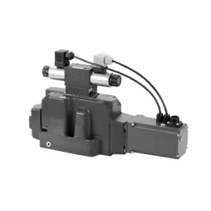

Den pilotstyrede proportionale retningsventil i 4WRKE-serien er en banebrydende hydraulisk komponent designet til at give overlegen præcision, kontrol og effektivitet i hydrauliske systemer. Med sin avancerede pilotstyrede proportionale styringsteknologi muliggør denne ventil præcis flowregulering og problemfri retningsændringer.
Den pilotstyrede proportionale retningsventil i 4WRKE-serien giver hydrauliske systemer præcis flowkontrol, alsidige retningsændringer og energieffektivitet. Dens pilotstyrede proportionale styringsteknologi sikrer præcis og responsiv flowjustering, mens den høje flowkapacitet garanterer pålidelig ydeevne, selv i krævende applikationer. Ved at følge de anbefalede brugsmetoder og vedligeholdelsesretningslinjer kan du maksimere fordelene og levetiden ved 4WRKE-seriens ventil og løfte dit hydrauliske system til nye niveauer af præcision og kontrol. Opgrader din hydrauliske opsætning i dag, og oplev kraften i den pilotstyrede proportionale retningsventil i 4WRKE-serien.
4WRKE-seriens pilotstyrede proportionale retningsbestemte hydrauliske ventil. Nøgleegenskaber:
- Pilotstyret proportionalstyring
- 4WRKE-serien af ventiler anvender pilotstyret proportionalstyringsteknologi, der muliggør præcis og proportional flowjustering baseret på styresignaler.
- Denne funktion sikrer præcis og responsiv styring, hvilket resulterer i forbedret systemydelse, reduceret energiforbrug og øget produktivitet.
- Alsidig retningskontrol
- Denne ventil tilbyder alsidig kontrol over hydraulikvæskens retning, hvilket gør den velegnet til en bred vifte af anvendelser.
- Det muliggør problemfri aktivering og deaktivering af hydrauliske komponenter såsom cylindre, motorer og aktuatorer i forskellige retninger, hvilket forbedrer systemets fleksibilitet og tilpasningsevne.
- Høj flowkapacitet
- 4WRKE-seriens ventil er konstrueret til at håndtere høje flowhastigheder, hvilket gør den ideel til applikationer, der kræver betydelig hydraulisk kraft.
- Dens robuste konstruktion sikrer pålidelig ydeevne selv under krævende forhold og giver ensartet og effektiv flowkontrol.
- Energieffektivitet
- Ved at indbygge pilotstyret proportionalstyring minimerer denne ventil trykfald og optimerer energiforbruget.
- Det hjælper med at reducere energiforbruget, hvilket resulterer i omkostningsbesparelser og miljømæssige fordele.
4WRKE-seriens pilotstyret proportional retningsbestemt hydraulisk ventil Parameter:
| Generel | |||||||||
| Størrelse | 10 | 16 | 25 | 27 | 32 | 35 | |||
| Retningslinjer for installation og idriftsættelse | valgfrit, helst vandret | ||||||||
| Opbevaringstemperaturområde | ℃ | – 20 til + 80 | |||||||
| Omgivelsestemperaturområde | ℃ | -20 til + 50 | |||||||
| Vægt | kg | 8.7 | 11.2 | 16.8 | 20 | 37.2 | 72 | ||
| Hydraulisk (målt ved p=100 bar, med HLP46 ved ϑoil = 40℃ ±5℃) | |||||||||
| Driftstryk | -Pilotkontrolventil | Pilotolieforsyning | bar | 25 til 315 | |||||
| -Hovedventil | Port PAB | bar | Op til 315 | Op til 350 | Op til 350 | Op til 210 | Op til 350 | Op til 350 | |
| Returtryk | Port T
(Pilotolieaftapning) |
Indre | bar | Statisk < 10 | |||||
| Ekstern | bar | Op til 315 | Op til 250 | Op til 250 | Op til 210 | Op til 250 | Op til 250 | ||
| Port Y | bar | Statisk < 10 | |||||||
| Nominel flow qVnom ±10% ved Δp=10 bar (Δp = ventiltrykforskel) |
l/min | 25 50 | – 125 | – 220 | – – | – 440 | – | ||
| 100 | 180 | 350 | 500 | 600 | 1000 | ||||
| Hovedventilens flow (maks. tilladt) | l/min | 170 | 460 | 870 | 1000 | 1600 | 3000 | ||
| Pilotolieflow ved port X eller Y med en trinvis form af indgangssignal fra 0 til 100 % (315 bar) | l/min | 4.1 | 8.5 | 11.7 | 11.7 | 13 | 13 | ||
| Trykvæske | Mineralolie (HL, HLP) i henhold til DIN 51 524 fosfatester (HFD-R) | ||||||||
| Væsketemperaturområde | ℃ | 10 til 80, helst 40 til 50 | |||||||
| Viskositetsområde | mm2/s | 20 til 380, helst 30 til 45 | |||||||
| Grad af forurening | Maksimal tilladt forureningsgrad: NAS 1638. | Et filter med en minimumsretentionshastighed på βx = 75 anbefales. | |||||||
| Pilotkontrolventil | Klasse 7 | x = 5 | |||||||
| Hovedventil | Klasse 9 | x = 7 | |||||||
| Hysterese | % | ≤1 | |||||||
| Responsfølsomhed | % | ≤0,5 | |||||||
| Elektrisk | |||||||||
| Spændingstype | DC | ||||||||
| Elektrisk tilslutning | Stikforbindelse i henhold til DIN EN175 201-804 | ||||||||
| Effekt, maks. | V | 72 (gennemsnit = 24W) | |||||||
| Styringselektronik | Integreret i ventilen | ||||||||
Fordele ved 4WRKE-seriens pilotstyrede proportionale retningsbestemte hydrauliske ventil:
• Pilotstyret to-trins proportional retningsventil med elektrisk positionsfeedback af hovedspolen, der bruges til at styre størrelsen og retningen af væskestrømmen
• Forbindelsesstruktur af underplademonteringstype, tilslutningsstørrelse overholder ISO 4401-standarden
• Fjedercentreret hovedspole
• Med integreret proportionalforstærker
• Pilotstyringen er en et-trins proportional retningsventil
• Pilotventilen er en gevindskåret proportional solenoid, og spolen kan adskilles separat.
Brugsmetode for 4WRKE-seriens pilotstyrede proportionale retningsbestemte hydrauliske ventil:
- Systemevaluering
- Evaluer dit hydrauliske system, og identificer de specifikke krav til flow- og retningsstyring.
- Afgør, om 4WRKE-seriens ventil er egnet baseret på dens flowkapacitet, trykklassificering og kompatibilitet med dit system.
- Valg af ventil
- Vælg den passende variant af 4WRKE-seriens ventil baseret på dine systemparametre, flowkrav og behov for retningsbestemt styring.
- Overvej faktorer som maksimal flowhastighed, trykklassificering, reaktionstid og driftsforhold.
- Installation
- Follow the manufacturer’s installation instructions carefully, ensuring proper alignment and secure mounting of the valve.
- Sørg for lækagefri forbindelser, og sørg for korrekt justering af strømningsretningen for at garantere optimal ydeevne.
- Tilslutning af styresignal
- Tilslut ventilens styresignalledninger til en passende styreenhed, såsom en proportionalforstærker eller elektronisk styreenhed.
- Sørg for korrekt ledningsføring og kompatibilitet mellem ventilen og styreenheden for at opnå præcis og responsiv styring.
Hvordan rengør man hydrauliske ventilløftere?
Cleaning hydraulic valve lifters is an important maintenance task that helps ensure proper engine performance and reduce noise caused by dirt or debris buildup. Here’s a step-by-step guide on how to clean hydraulic valve lifters:
- Saml de nødvendige værktøjer og materialer:
- Ny motorolie
- Rene klude eller håndklæder
- Motoraffedtningsmiddel eller delerenser
- Lille børste eller tandbørste
- Plastbeholder eller bakke
- Forberedelse:
- Lad motoren køle helt af, før du starter rengøringsprocessen.
- Remove the valve cover or covers to access the hydraulic valve lifters. Refer to the manufacturer’s instructions or a repair manual for your specific engine to locate and remove the valve cover(s) properly.
- Afmontering af hydrauliske ventilløftere:
- Identificér de hydrauliske ventilløftere i motoren.
- Fjern forsigtigt de hydrauliske ventilløftere én ad gangen fra deres respektive placeringer. Afhængigt af din motor kan det være nødvendigt at fjerne andre komponenter eller dele for at få adgang til løfterne.
- Placer hver løfter i en plastikbeholder eller -bakke i den rækkefølge, de blev fjernet. Dette vil hjælpe med at sikre, at de installeres korrekt senere.
- Rengøring af løfterne:
- Hæld en lille mængde motoraffedtningsmiddel eller delerens i en beholder.
- Placer en hydraulisk ventilløfter i beholderen, og sørg for, at den er helt nedsænket i rengøringsmidlet.
- Lad løfteren trække i den anbefalede tid, som producenten af rengøringsmidlet har angivet. Dette varierer normalt fra 15 minutter til en time.
- Use a small brush or toothbrush to gently scrub the lifter’s exterior surfaces, removing any deposits or dirt.
- Skyl løfteren grundigt med rent vand for at fjerne eventuelle rester af rengøringsmiddel eller snavs.
- Tør løfteren med en ren klud eller et håndklæde. Sørg for, at der ikke er spor af fugt, før den monteres igen.
- Geninstallation:
- Apply a small amount of fresh engine oil to the cleaned lifter’s exterior surface.
- Placer forsigtigt løfteren tilbage i sin oprindelige position i motoren, og sørg for, at den er korrekt justeret og på plads.
- Gentag rengøringsprocessen for hver hydraulisk ventilløfter, idet du følger de samme trin.
- Når alle løfteanordningerne er rengjort og monteret igen, skal du sørge for, at de er ordentligt fastgjort.
- Genmontering:
- Reinstall the valve cover(s) according to the manufacturer’s instructions.
- Dobbelttjek, at alle komponenter og dele er korrekt fastgjort og strammet.
- Test og inspektion:
- Start motoren, og lad den køre i et par minutter for at sikre korrekt drift og for at lade løfterne fylde op med olie.
- Lyt efter unormale lyde eller tikkelyde, der kan indikere yderligere problemer.
- Hvis støj- eller ydeevneproblemer fortsætter, kan det være nødvendigt at konsultere en professionel mekaniker for yderligere diagnose og reparation.
Fabrikkens kapacitet og kapacitet:
(1) Samling
Vi har en førsteklasses uafhængig forsknings- og udviklingsplatform til montering. Værkstedet for produktion af hydrauliske cylindre har fire halvautomatiske løftecylindermonteringslinjer og en automatisk vippecylindermonteringslinje med en designmæssig årlig produktionskapacitet på 1 million enheder. Det specielle cylinderværksted er udstyret med forskellige specifikationer for et halvautomatisk rengøringsmonteringssystem med en designmæssig årlig produktionskapacitet på 200.000 og udstyret med berømt CNC-bearbejdningsudstyr, et bearbejdningscenter, et specialudstyr til højpræcisionscylinderbearbejdning, en robotsvejsemaskine, en automatisk rengøringsmaskine, en automatisk cylindermonteringsmaskine og en automatisk malingslinje. Eksisterende kritisk udstyr på mere end 300 sæt (sæt). Optimal allokering og effektiv udnyttelse af udstyrsressourcer sikrer produkternes nøjagtighedskrav og opfylder produkternes høje kvalitetsbehov.


(2) Maskinbearbejdning
Bearbejdningsværkstedet er udstyret med et specialfremstillet drejecenter til skrå skinner, bearbejdningscenter, højhastigheds-honemaskine, svejserobot og andet relateret udstyr, der kan håndtere bearbejdning af cylinderrør med en maksimal indre diameter på 400 mm og en maksimal længde på 6 meter.


(3) Svejsning


(4) Maling og overfladebehandling
Med små og mellemstore cylindriske automatiske vandbaserede malingsbelægningslinjer, for at opnå automatisk robotpåfyldning og -aflæsning samt automatisk sprøjtning, er den designmæssige kapacitet på 4000 stykker pr. skift;
Vi har også en halvautomatisk malingsproduktionslinje til store cylindre drevet af en kabelkæde med en designkapacitet på 60 kasser pr. skift.


(5) Testning
Vi har førsteklasses inspektionsfaciliteter og testbænke for at sikre, at cylinderens ydeevne opfylder kravene.


Vi er en af de bedste producenter af hydrauliske cylindre. Vi kan tilbyde et omfattende udvalg af hydrauliske cylindre. Vi leverer også tilsvarende landbrugsgearkasserVi har eksporteret vores produkter til kunder over hele verden og har opnået et godt omdømme på grund af vores overlegne produktkvalitet og eftersalgsservice. Vi byder kunder i ind- og udland velkommen til at kontakte os for at forhandle forretninger, udveksle information og samarbejde med os!