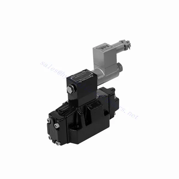
GWEH-serien eksplosionssikker retningsbestemt hydraulisk ventil
Som en af producenterne, leverandørerne og eksportørerne af mekaniske produkter tilbyder vi hydrauliske cylindre og mange andre produkter.
Kontakt os for yderligere oplysninger.
Mail:sales@hydraulic-cylinders.net
Producent, leverandør og eksportør af hydrauliske cylindre.
GWEH-serien eksplosionssikker retningsbestemt hydraulisk ventil
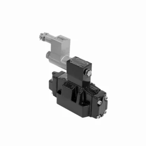
The GWEH series explosion-proof directional hydraulic valve is an innovative solution designed to provide optimal safety and precise control in hydraulic systems operating in hazardous environments. With its explosion-proof features, reliable performance, and advanced functionalities, this valve offers enhanced safety measures, efficient fluid flow control, and compatibility with various industrial applications.
The GWEH series explosion-proof directional hydraulic valve is a reliable and efficient solution for industries operating in hazardous environments. With its explosion-proof design, precise directional control, versatility, and high performance, this valve ensures safety and control in hydraulic systems. Following the recommended usage methods and adhering to regular maintenance practices, the GWEH series valve delivers safe and efficient operation in explosive atmospheres. Upgrade your hydraulic system with the GWEH series explosion-proof directional hydraulic valve and experience enhanced safety, optimal fluid flow control, and reliable performance.
GWEH Series Explosion-proof Directional Hydraulic Valve Key Characteristics:
- Explosion-proof Design:
- The GWEH series valve is engineered with a robust explosion-proof design, ensuring safe operation in environments containing flammable gases or dust.
- It complies with stringent safety standards and certifications, minimizing the risk of ignition and ensuring the safety of personnel and equipment.
- Retningskontrol:
- This hydraulic valve provides precise directional control of fluid flow, allowing for the activation and deactivation of specific hydraulic actuators.
- It enables smooth and reliable operation of various hydraulic functions, such as cylinder extension and retraction or motor direction changes.
- Versatility and Compatibility:
- The GWEH series valve is highly versatile and compatible with various hydraulic systems and applications.
- It can seamlessly integrate into industrial machinery, mobile equipment, and automation systems operating in hazardous environments.
- Høj ydeevne:
- With its advanced design and high-quality construction, the GWEH series hydraulic valve delivers exceptional performance and reliability.
- It ensures consistent and precise control over fluid flow, contributing to efficient and optimized system operation.
GWEH Series Explosion-proof Directional Hydraulic Valve Parameter:
NG10
| Working pressureP,A,B | bar | 315 | |||||||||
| Port T | With external pilot oil drain | bar | 315 | ||||||||
| With internal pilot oil drain | bar | 210 | |||||||||
| Port Y | With external pilot oil drain | bar | 210 | ||||||||
| Min. control pressure | With external pilot oil supply
With internal pilot oil supply (not apply to C, Z, F, G, H, P, T, V) |
bar | 3-position valve 10 | ||||||||
| Spring-return 2-position valve 10 | |||||||||||
| Hydraulic-return 2-position valve 7 | |||||||||||
| With internal pilot oil supply ( apply to C, Z, F, G, H, P, T, V) |
bar | 4.5 | |||||||||
| Max. control pressure | bar | 250 | |||||||||
| Væske | Mineralolie, fosfatester | ||||||||||
| Væsketemperaturområde | ℃ | -30 to +80 ( NBR seals | |||||||||
| -20 to +80 ( FKM seals ) | |||||||||||
| Viskositetsområde | mm2/s | 2,8 til 500 | |||||||||
| Controlled quantity in commutating process | cm3 | 3-position valve 2.04 2-position valve 4.08 | |||||||||
| Switching times (= Valve switching time from the neutral position to the switched position)(DC ) | |||||||||||
| Control pressure | bar | 70 | 140 | 210 | 250 | ||||||
| 3-position valve | ms | 65 | 60 | 55 | 50 | ||||||
| 2-position valve | ms | 80 | 75 | 70 | 65 | ||||||
| Switching times (= Valve switching time from the switched position to the neutral position) | |||||||||||
| 3-position valve | ms | 30 | |||||||||
| 2-position valve | ms | 35 | 40 | 30 | 35 | 25 | 30 | 20 | 25 | ||
| Flow of shortest switching time | l/min | about 35 | |||||||||
| Installationsposition | HC, HD, HK, HZ and HY of hydraulic return shall be installed horizontally. The rest are arbitrary | ||||||||||
NG16
| Specifikationer | G-..WEH16../6B2.. type | |||||||
| Working pressureP,A,B bar | 350 | |||||||
| Port T | With external pilot oil drain bar | 250 | ||||||
| With internal pilot oil drain bar | 210 | |||||||
| Hydraulic-centering 3-position valve With internal pilot oil drain is impossible | ||||||||
| Port Y | With external pilot oil drain bar | 210 | ||||||
| Min. control pressure | With external pilot oil supply bar
With internal pilot oil supply bar |
3-position valve 14 | ||||||
| Spring-return 2-position valve 14 | ||||||||
| Hydraulic-return 2-position valve 14 | ||||||||
| With internal pilot oil supply ( apply to C、Z、F、G、H、P、T、V) bar |
When applying back pressure valve or the flow is large, enginery of spool valve is 4.5 bar as C、Z、F、G、H、P、T and V | |||||||
| Max. control pressure bar | 250 | |||||||
| Væske | Mineralolie, fosfatester | |||||||
| Fluid temperature range ℃ | -30 to +80 ( NBR seals | |||||||
| -20 to +80 ( FKM seals ) | ||||||||
| Viscosity range mm2 /s 2 | 2.8 to 500 | |||||||
| Switching pilot oil volume | ||||||||
| -Spring-centering 3-position valve cm3 | 5.72 | |||||||
| -2-position valve cm3 | 11.45 | |||||||
| * Switching times (= Valve switching time from the neutral position to the switched position)(AC and DC) | ||||||||
| Control pressure bar | 50 | 150 | 250 | |||||
| – Spring-centering 3-position valve ms | 65 | 60 | 58 | |||||
| – 2-position valve ms | 65 | 55 | 50 | |||||
| *Switching times (= Valve switching time from the neutral position to the switched position) | ||||||||
| – Spring-centering 3-position valve ms | 40 | |||||||
| – 2-position valve ms | 45 | 35 | 30 | |||||
| Installationsposition | C,D,K,Z,Y Type hydraulic-return valves are installed horizontally, the rest can be installed arbitrarily。 | |||||||
| Flow of shorter switching time L/min | about 35 | |||||||
| Weight of the valve kg | about 10.6 | |||||||
NG25
| Specifikationer | G-H-…WEH25../6B2… type | |||||||||
| Working pressureP,A,B bar | 350 | |||||||||
| Port T | With external pilot oil drain bar | 250 | ||||||||
| With internal pilot oil drain bar | 210 | |||||||||
| Hydraulic-centering 3-position valve With internal pilot oil drain is impossible | ||||||||||
| Port Y | With external pilot oil drain bar | 210 | ||||||||
| Min. control pressure | With external pilot oil supply bar
With internal pilot oil supply bar |
Spring-centering 3-position valve 13 | ||||||||
| Hydraulic-centering 3-position valve 18 | ||||||||||
| Spring-return 2-position valve 13 | ||||||||||
| Hydraulic-return 2-position valve 18 | ||||||||||
| With internal pilot oil supply | When applying back pressure valve or the flow is large, enginery of spool valve is 4.5 bar as C、Z、F、G、H、P、T and V | |||||||||
| Max. control pressure bar | 250 | |||||||||
| Væske | Mineralolie, fosfatester | |||||||||
| Fluid temperature range ℃ | -30 to +80 ( NBR seals | |||||||||
| -20 to +80 ( FKM seals ) | ||||||||||
| Viscosity range mm2 /s 2 | 2.8 to 500 | |||||||||
| Switching pilot oil volume | ||||||||||
| -Spring-centering 3-position valve cm3 | 14.2 | |||||||||
| -2-position valve cm3 | 28.4 | |||||||||
| * Switching times (= Valve switching time from the neutral position to the switched position)(AC and DC) | ||||||||||
| Control pressure bar | 50 | 140 | 210 | 250 | ||||||
| – Spring-centering 3-position valve ms | 85 | 75 | 70 | 65 | ||||||
| – 2-position valve ms | 160 | 130 | 120 | 105 | ||||||
| **Switching times (= Valve switching time from the neutral position to the switched position) | ||||||||||
| – Spring-centering 3-position valve ms | 40 | |||||||||
| – 2-position valve ms | 125 | 100 | 90 | 80 | ||||||
| Installationsposition | C,D,K,Z,Y Type hydraulic-return valves are installed horizontally, the rest can be installed arbitrarily。 | |||||||||
| Flow of shorter switching time L/min | about 35 | |||||||||
| Weight of the valve kg | about 19 | |||||||||
GWEH Series Explosion-proof Directional Hydraulic Valve Advantages:
• Directional valve directional the oil path by controlling the main spool
• WEH electrohydraulic control
• Two-position four-way or three-position four-way
• Installation face follows DIN 24340 A, ISO 4401, and CETOP-RP 121H Sub-plate mounting connection
• Udskift spolen uden at udlede olie
Usage Method Of GWEH Series Explosion-proof Directional Hydraulic Valve :
- Hazardous Area Assessment:
- Conduct a thorough assessment of the hazardous area to identify the specific explosion-proof requirements and classification.
- Determine the appropriate safety measures and precautions needed to comply with the regulations.
- Valg af ventil:
- Select the GWEH Series Valve with the suitable specifications, considering factors such as pressure ratings, flow capacity, and voltage requirements.
- Ensure compatibility with the hydraulic system and the specific hazardous environment.
- Installation:
- Follow the manufacturer’s instructions for proper installation of the GWEH Series Valve in the hydraulic system.
- Ensure secure mounting and proper electrical connections, adhering to the recommended torque values and wiring guidelines.
- Control and Activation:
- Utilize the recommended control method, such as electrical signals or remote activation, to operate the GWEH Series Valve.
- Connect the valve to a suitable power source and control system, following the provided wiring diagrams.
How Does A Hydraulic Control Valve Work?
A hydraulic control valve is a critical component in hydraulic systems that regulates the flow and direction of hydraulic fluid to control the operation of hydraulic actuators. It enables precise control over various hydraulic functions, such as extending or retracting cylinders, controlling motor speed and direction, or adjusting the flow rate of hydraulic fluid. Here’s an overview of how a hydraulic control valve works:
- Ventilstruktur:
- A hydraulic control valve typically consists of a valve body, spools or poppets, and various internal passages.
- The valve body contains inlet and outlet ports for fluid connection and chambers that direct the flow.
- The spools or poppets are movable elements within the valve body that control the flow paths and connect the appropriate ports.
- Flowkontrol:
- The hydraulic control valve regulates the flow of hydraulic fluid by opening and closing specific flow paths within the valve.
- The position of the spools or poppets determines which ports are connected and allows fluid to flow in the desired direction.
- Retningskontrol:
- Hydraulic control valves provide directional control by selectively connecting or blocking fluid flow to different hydraulic actuators.
- By adjusting the position of the spools or poppets, the valve determines which actuator receives fluid and in which direction it moves.
- Actuation Methods:
- Hydraulic control valves can be actuated using manual levers, mechanical linkages, solenoids, or pilot pressure control.
- Manual control valves are operated by moving the levers or handles to position the spools or poppets.
- Solenoid-controlled valves use electromagnetic coils to actuate the valve, allowing for remote or automated control.
- Control Modes:
- Hydraulic control valves offer different control modes, such as 2-way, 3-way, or 4-way control.
- A 2-way control valve controls flow in one direction, allowing or blocking fluid flow.
- A 3-way control valve has three ports and can control the flow between two ports while blocking the third.
- A 4-way control valve has four ports and can route fluid between two actuator ports while blocking the other two.
- Trykkompensation:
- Some hydraulic control valves are equipped with pressure compensation features to maintain a consistent flow rate despite changes in system pressure.
- These valves adjust the flow passages based on pressure differentials, allowing for precise control regardless of varying operating conditions.
- Feedback and Control Loops:
- Advanced hydraulic control valves may incorporate feedback mechanisms, such as position or pressure sensors, to provide feedback to a control system.
- This feedback enables closed-loop control, where the system can monitor and adjust the valve’s position or flow based on desired setpoints or operating conditions.
Fabrikkens kapacitet og kapacitet:
(1) Samling
Vi har en førsteklasses uafhængig forsknings- og udviklingsplatform til montering. Værkstedet for produktion af hydrauliske cylindre har fire halvautomatiske løftecylindermonteringslinjer og en automatisk vippecylindermonteringslinje med en designmæssig årlig produktionskapacitet på 1 million enheder. Det specielle cylinderværksted er udstyret med forskellige specifikationer for et halvautomatisk rengøringsmonteringssystem med en designmæssig årlig produktionskapacitet på 200.000 og udstyret med berømt CNC-bearbejdningsudstyr, et bearbejdningscenter, et specialudstyr til højpræcisionscylinderbearbejdning, en robotsvejsemaskine, en automatisk rengøringsmaskine, en automatisk cylindermonteringsmaskine og en automatisk malingslinje. Eksisterende kritisk udstyr på mere end 300 sæt (sæt). Optimal allokering og effektiv udnyttelse af udstyrsressourcer sikrer produkternes nøjagtighedskrav og opfylder produkternes høje kvalitetsbehov.


(2) Maskinbearbejdning
Bearbejdningsværkstedet er udstyret med et specialfremstillet drejecenter til skrå skinner, bearbejdningscenter, højhastigheds-honemaskine, svejserobot og andet relateret udstyr, der kan håndtere bearbejdning af cylinderrør med en maksimal indre diameter på 400 mm og en maksimal længde på 6 meter.

(3) Svejsning

(4) Maling og overfladebehandling
Med små og mellemstore cylindriske automatiske vandbaserede malingsbelægningslinjer, for at opnå automatisk robotpåfyldning og -aflæsning samt automatisk sprøjtning, er den designmæssige kapacitet på 4000 stykker pr. skift;
Vi har også en halvautomatisk malingsproduktionslinje til store cylindre drevet af en kabelkæde med en designkapacitet på 60 kasser pr. skift.


(5) Testning
Vi har førsteklasses inspektionsfaciliteter og testbænke for at sikre, at cylinderens ydeevne opfylder kravene.

Vi er en af de bedste producenter af hydrauliske cylindre. Vi kan tilbyde et omfattende udvalg af hydrauliske cylindre. Vi leverer også tilsvarende landbrugsgearkasserVi har eksporteret vores produkter til kunder over hele verden og har opnået et godt omdømme på grund af vores overlegne produktkvalitet og eftersalgsservice. Vi byder kunder i ind- og udland velkommen til at kontakte os for at forhandle forretninger, udveksle information og samarbejde med os!
Hydraulisk cylinderanvendelse:
