
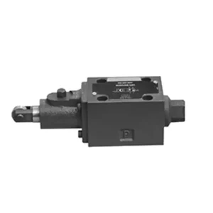
WMR-seriens retningsbestemte hydrauliske ventil med mekanisk, manuel betjening
Som en af producenterne, leverandørerne og eksportørerne af mekaniske produkter tilbyder vi hydrauliske cylindre og mange andre produkter.
Kontakt os for yderligere oplysninger.
Mail:sales@hydraulic-cylinders.net
Producent, leverandør og eksportør af hydrauliske cylindre.
WMR-seriens retningsbestemte hydrauliske ventil med mekanisk, manuel betjening
The WMR series directional hydraulic valve with mechanical, manual operation is a cutting-edge solution designed to deliver precise control in hydraulic systems. This valve offers enhanced efficiency and flexibility with its advanced features and robust construction.
The WMR series directional hydraulic valve with mechanical, manual operation is a reliable and versatile solution for hydraulic systems. Its automatic and manual operation and precise directional control offer enhanced flexibility and control for various applications. Following the recommended usage methods and adhering to regular maintenance practices, the WMR series valve will continue providing efficient and reliable operation. Upgrade your hydraulic system with the WMR series directional hydraulic valve and experience the benefits of enhanced control and versatility.
WMR Series Directional Hydraulic Valve With Mechanical, Manual Operation Key Characteristics:
- Mechanical, Manual Operation:
- The WMR series valve features a mechanical, manual operation, allowing operators to control the valve position manually.
- This provides flexibility and control in applications where manual operation is desired or required.
- Retningskontrol:
- This hydraulic valve enables precise directional fluid flow control within the hydraulic system.
- It allows operators to select the desired flow path, ensuring efficient and reliable operation.
- Holdbar konstruktion:
- The WMR series valve is constructed with high-quality materials, ensuring durability and longevity.
- Its robust design can withstand demanding operating conditions, providing reliable performance.
- Bredt anvendelsesområde:
- The WMR series valve suits various industries and applications, including manufacturing, construction, agriculture, etc.
- It can be utilized in hydraulic systems that require accurate and efficient fluid control.
WMR Series Directional Hydraulic Valve With Mechanical, Manual Operation Parameter:
NG6
| Installationsposition | Valgfri | ||
| Væsketemperaturområde | ℃ | -30 til +80 (NBR-tætninger) | |
| -20 til +80 (FKM-tætninger) | |||
| Port Max. operating pressure | Port A B P | bar | 315 |
| Port T | bar | 60 | |
| Maks. flowhastighed | l/min | 60 | |
| Flow cross section (switching neutral position) | Q type | mm2 | For symbol Q, 6% of the nominal cross-section |
| W type | mm2 | For symbol W, 3% of the nominal cross-section | |
| Væske | Mineralolie; Fosfatester | ||
| Viskositetsområde | mm2/s | 2.8 to 500 | |
| Grad af forurening | Maksimal tilladt grad af væskeforurening: Klasse 9. NAS 1638 eller 20/18/15, ISO4406 | ||
| Vægt | kg | 1.4 | |
NG10
| Installationsposition | Valgfri | ||
| Væsketemperaturområde | ℃ | -30 til +80 (NBR-tætninger) | |
| -20 til +80 (FKM-tætninger) | |||
| Port Max. operating pressure | Port A B P | bar | 315 |
| Port T | bar | 60 | |
| Maks. flowhastighed | l/min | 120 | |
| Flow cross section (switching neutral position) | V type | mm2 | 11(A/B → T);10,3(P → A/B) |
| W type | mm2 | 2,5(A/B → T) | |
| Q type | mm2 | 5,5(A/B → T) | |
| Væske | Mineralolie; Fosfatester | ||
| Viskositetsområde | mm2/s | 2.8 to 500 | |
| Grad af forurening | Maksimal tilladt grad af væskeforurening: Klasse 9. NAS 1638 eller 20/18/15, ISO4406 | ||
| Vægt | kg | 4 | |
WMR Series Directional Hydraulic Valve With Mechanical, Manual Operation Advantages:
• Direct-acting directional slide valve direct-acting directional slide valve
• Scroll wheel can rotate 90°
• Nineteen standard slide valve functions
Usage Method Of WMR Series Directional Hydraulic Valve With Mechanical, Manual Operation:
- Systemintegration:
- Identify the appropriate location for the WMR series valve within the hydraulic system, considering the desired flow direction and control requirements.
- Sørg for kompatibilitet med systemets tryk- og flowspecifikationer.
- Monter ventilen sikkert med passende beslag eller monteringstilbehør.
- Væskeforbindelser:
- Vælg kompatible hydrauliske fittings og slanger for sikre og lækagefri forbindelser.
- Følg producentens anvisninger for korrekte momentværdier under installationsprocessen.
- Brug passende gevindtætningsmidler eller tape for at sikre en pålidelig tætning.
- Manual Operation:
- Familiarize yourself with the manual operation mechanism of the valve, including the lever or knob used to control the valve position.
- Ensure the operator understands the correct procedure for manually adjusting the valve position.
- Systemkalibrering:
- Calibrate the valve position and movement according to the desired flow direction and control requirements.
- Adjust the valve manually to achieve the desired flow path and ensure proper functionality.
How To Adjust Hydraulic Valve Lifters?
Adjusting hydraulic valve lifters is a crucial maintenance task to ensure proper engine performance and prevent issues like valve train noise and reduced power. Here’s a step-by-step guide on how to adjust hydraulic valve lifters:
- Prepare the Engine:
- Before starting the adjustment process, make sure the engine is turned off and cool to the touch.
- Remove any components necessary to access the valve covers, such as the air cleaner assembly or spark plug wires.
- Identify the Correct Valve Adjustment Sequence:
- Consult the engine manufacturer’s specifications or service manual to determine the correct valve adjustment sequence for your specific engine.
- Some engines have a firing order that dictates the sequence, while others have specific instructions based on cylinder numbering.
- Locate the Top Dead Center (TDC) Position:
- Rotate the engine’s crankshaft in the normal direction of rotation until the number one piston reaches the top dead center (TDC) position on its compression stroke.
- Use a timing mark on the harmonic balancer or flywheel and a timing pointer to determine the TDC position accurately.
- Adjusting Valve Lifters:
- Start with the first cylinder in the valve adjustment sequence.
- Remove the valve cover to access the rocker arms and valve lifters.
- Loosen the lock nut on the rocker’s arm using an appropriate wrench or socket.
- Turn the adjusting screw or stud on the rocker’s arm clockwise to decrease the valve clearance or counterclockwise to increase it.
- Check the engine manufacturer’s specifications for the recommended valve clearance. Use a feeler gauge to measure the clearance between the rocker arm and the valve stem.
- Adjust the valve lifter until the proper clearance is achieved. You should feel slight resistance but still be able to move the feeler gauge back and forth.
- Hold the adjusting screw or stud in place and tighten the lock nut securely.
- Gentag processen:
- Move to the next cylinder in the valve adjustment sequence and repeat steps 4 and 5 until all the valve lifters have been adjusted.
- Reinstall Valve Covers:
- Once you’ve completed the valve adjustment on all cylinders, reinstall the valve covers and ensure they are properly sealed to prevent oil leaks.
- Double-Check:
- After adjusting the valve lifters, it’s advisable to go through the entire valve adjustment sequence once more to confirm that all clearances are within the specified range.
Fabrikkens kapacitet og kapacitet:
(1) Samling
Vi har en førsteklasses uafhængig forsknings- og udviklingsplatform til montering. Værkstedet for produktion af hydrauliske cylindre har fire halvautomatiske løftecylindermonteringslinjer og en automatisk vippecylindermonteringslinje med en designmæssig årlig produktionskapacitet på 1 million enheder. Det specielle cylinderværksted er udstyret med forskellige specifikationer for et halvautomatisk rengøringsmonteringssystem med en designmæssig årlig produktionskapacitet på 200.000 og udstyret med berømt CNC-bearbejdningsudstyr, et bearbejdningscenter, et specialudstyr til højpræcisionscylinderbearbejdning, en robotsvejsemaskine, en automatisk rengøringsmaskine, en automatisk cylindermonteringsmaskine og en automatisk malingslinje. Eksisterende kritisk udstyr på mere end 300 sæt (sæt). Optimal allokering og effektiv udnyttelse af udstyrsressourcer sikrer produkternes nøjagtighedskrav og opfylder produkternes høje kvalitetsbehov.


(2) Maskinbearbejdning
Bearbejdningsværkstedet er udstyret med et specialfremstillet drejecenter til skrå skinner, bearbejdningscenter, højhastigheds-honemaskine, svejserobot og andet relateret udstyr, der kan håndtere bearbejdning af cylinderrør med en maksimal indre diameter på 400 mm og en maksimal længde på 6 meter.

(3) Svejsning

(4) Maling og overfladebehandling
Med små og mellemstore cylindriske automatiske vandbaserede malingsbelægningslinjer, for at opnå automatisk robotpåfyldning og -aflæsning samt automatisk sprøjtning, er den designmæssige kapacitet på 4000 stykker pr. skift;
Vi har også en halvautomatisk malingsproduktionslinje til store cylindre drevet af en kabelkæde med en designkapacitet på 60 kasser pr. skift.


(5) Testning
Vi har førsteklasses inspektionsfaciliteter og testbænke for at sikre, at cylinderens ydeevne opfylder kravene.

Vi er en af de bedste producenter af hydrauliske cylindre. Vi kan tilbyde et omfattende udvalg af hydrauliske cylindre. Vi leverer også tilsvarende landbrugsgearkasserVi har eksporteret vores produkter til kunder over hele verden og har opnået et godt omdømme på grund af vores overlegne produktkvalitet og eftersalgsservice. Vi byder kunder i ind- og udland velkommen til at kontakte os for at forhandle forretninger, udveksle information og samarbejde med os!
Hydraulisk cylinderanvendelse:
