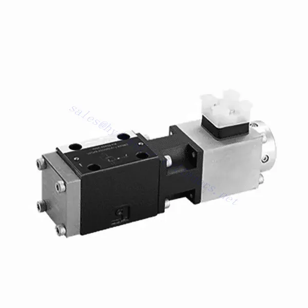
DBE6X(E) Series Proportional Pressure Relief Hydraulic Valve
DBE6X(E) Series Proportional Pressure Relief Hydraulic Valve
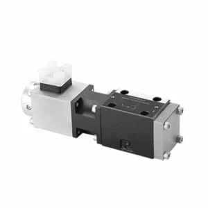
The DBE6X(E) series proportional pressure relief hydraulic Valve is a cutting-edge component that provides accurate and dynamic pressure control in hydraulic systems. With its advanced proportional control technology, this valve ensures optimal performance, efficiency, and safety.
The DBETX series proportional pressure relief hydraulic valve empowers hydraulic systems with precise pressure control, enhanced efficiency, and equipment protection. With its commensurate pressure relief capabilities, this valve ensures optimal performance across various applications. By following the recommended usage methods and maintenance guidelines, you can maximize the benefits and reliability of the DBETX series valve, elevating the performance and control of your hydraulic system. Upgrade your hydraulic setup today and experience superior pressure regulation with the DBETX series proportional pressure relief hydraulic valve.
DBE6X(E) Series Proportional Pressure Relief Hydraulic Valve Key Characteristics:
- Proportional Pressure Relief:
- The DBE6X(E) series valve offers precise and proportional pressure relief, allowing dynamic hydraulic pressure control.
- It ensures accurate pressure regulation in response to varying load conditions, preventing system overload and safeguarding hydraulic components.
- Verbesserte Systemeffizienz:
- This valve enables precise hydraulic pressure control, resulting in enhanced system efficiency and reduced energy consumption.
- By maintaining the desired pressure levels, it minimizes pressure fluctuations, optimizes system performance, and reduces operational costs.
- Safety and Equipment Protection:
- The DBE6X(E) Series Valve acts as a protective mechanism by limiting the pressure within the hydraulic system, safeguarding equipment and operators.
- It prevents excessive pressure build-up, reducing the risk of component damage, system failures, and potential accidents.
- Proportional Control Functionality:
- With its proportional control technology, the DBE6X(E) series valve offers smooth and precise pressure adjustment.
- It allows for real-time pressure control, enabling seamless integration into various hydraulic systems and applications.
DBE6X(E) Series Proportional Pressure Relief Hydraulic Valve Parameter:
| Allgemein | ||||||
| Konstruktion | Pilotphase | Tellerventil | ||||
| Hauptbühne | Schieberventil | |||||
| Betätigung | Proportionalmagnet ohne Positionsregelung, externer Verstärker | |||||
| Anschlussart | Unterplatte, Montagelochkonfiguration NG6 (SIO 4401-03-02-094) | |||||
| Einbaulage | Optional | |||||
| Umstände Temperaturbereich | ℃ | -20 bis +50 | ||||
| Gewicht | Kg | 2.2 | ||||
| Vibrationsfestigkeit, Prüfbedingungen | Max. 25 g, in 3 Dimensionen geschüttelt (24 h) | |||||
| Hydraulisch (gemessen mit HLP 46, Öl = 40℃ ±5℃ ): | ||||||
| Druckflüssigkeit | Hydraulic oil to DIN 51524…535,other fluids after prior consultation | |||||
| Viskositätsbereich | empfohlen | mm²/s | 20…100 | |||
| max. zulässig | mm²/s | 10…800 | ||||
| Druckflüssigkeitstemperaturbereich | ℃ | -20 bis +80 | ||||
| Maximal zulässiger Verschmutzungsgrad der Druckflüssigkeit Reinheitsklasse nach ISO 4406 (c) | Klasse 18/16/13 | |||||
| Strömungsrichtung | Siehe Symbol | |||||
| Maximaler Einstelldruck (bei Qmaxx = 1 l/min) | Bar | 80 | 180 | 250 | 315 | |
| Min. einstellbarer Druck(当 Qmin = 1 L/min) | Bar | 7 | 8 | 9 | 10 | |
| Max. Betriebsdruck | Bar | Port P:315 | ||||
| Port T: 250 | ||||||
| Maximaler mechanischer Druckgrenzwert, z. B. wenn der Magnetspulenstrom I > Imax ist. | Bar | < 90 | < 190 | < 260 | < 235 | |
| Pilotölfluss | L/min | etwa 0,6 | ||||
| Max. Durchfluss | L/min | 40 | ||||
| Elektrische Daten | ||||||
| Faktor der Zyklusdauer | % | 100 ED | ||||
| Schutzart | IP 65 nach DIN 40050 und IEC 14434/5 | |||||
| Magnetventilanschluss | Steckverbinder nach DIN 43650/ISO 4400, M16x1,5 (2P+PE) | |||||
| Ventil mit Magnetventil | 0,8A | 2,5 A | ||||
| Maximaler Magnetspulenstrom | Imax | 0,8A | 2,5 A | |||
| Spulenwiderstand R20 | Ω | 22 | 3 | |||
| Maximale Leistungsaufnahme bei 100%-Last und Betriebstemperatur | VA | 25 | 30 | |||
| Statisch/Dynamisch | ||||||
| Hysterese | % | ≤ 4 | ||||
| Inversionsbereich | % | ≤3 | ||||
| Fertigungstoleranz für Pmax | % | ≤10 | ||||
| Reaktionszeit 100% Signaländerung | MS | Ein 200 / Aus | ||||
DBE6X(E) Series Proportional Pressure Relief Hydraulic Valve Advantages:
• Pilotventil zur Begrenzung des Systemdrucks (nur interne Ölsteuerung)
• Kann durch Steuerung des Spulenstroms gemäß der Kennlinie und der gewählten elektronischen Steuereinheit angepasst werden
• Magnetspule Typ Imax=0,8 A oder 2,5 A
• Im Falle eines Ausfalls des elektronischen Steuergeräts kann der Überlastschutz maximal funktionieren (Spulenstrom > Imax).
• Wird bei der Montage von Ventilunterplatten verwendet, die Montagebohrung entspricht ISO 441-03-02-0-94.
• Kabelbuchsen entsprechen DIN 43650-AM2
• Externe elektronische Steuereinheit mit Rampen- und Ventilverstellfunktion VT-SSPA1-508/525-L2X/V0/*
Usage Method Of DBE6X(E) Series Proportional Pressure Relief Hydraulic Valve:
- Systembewertung:
- Bewerten Sie Ihr Hydrauliksystem und ermitteln Sie die spezifischen Anforderungen an die Druckregelung.
- Determine if the DBE6X(E) series valve is compatible with your system based on its pressure range, flow capacity, and other specifications.
- Ventilauswahl:
- Choose the appropriate DBE6X(E) series valve variant based on your system parameters, pressure range, and flow requirements.
- Berücksichtigen Sie die maximale Druckfestigkeit, die Ansprechzeit und die Betriebsbedingungen.
- Installation:
- Befolgen Sie die Installationsanweisungen des Herstellers sorgfältig und achten Sie auf die korrekte Ausrichtung und sichere Montage des Ventils.
- Schließen Sie das Ventil an das Hydrauliksystem an und achten Sie dabei auf leckagefreie Verbindungen und die korrekte Ausrichtung der Durchflussrichtung.
- Druckeinstellung:
- Utilize the proportional control signal or adjustment mechanism provided with the DBE6X(E) series valve to set the desired pressure relief level.
- Adjust the valve incrementally, monitoring the pressure gauge readings and system response to achieve precise pressure control.
How To Adjust Hydraulic Flow Control Valve?
Adjusting a hydraulic pressure relief valve allows you to set the desired maximum pressure in a hydraulic system. This is important for maintaining system integrity and preventing damage to components. Here’s a step-by-step guide on how to adjust a hydraulic pressure relief valve:
- Identify the Pressure Relief Valve:
- Locate the pressure relief valve in your hydraulic system. It is typically installed in the hydraulic line and often near the pump or control valve.
- Understand the Valve Design:
- Familiarize yourself with the specific design of the pressure relief valve you are working with. Different valves may have varying adjustment mechanisms, such as a knob, screw, or locknut.
- Determine the Desired Pressure:
- Assess the requirements of your hydraulic system and determine the desired maximum pressure. This will guide you in adjusting the pressure relief valve accurately.
- Bereiten Sie das System vor:
- Before making any adjustments, shut off the hydraulic system and relieve the pressure by moving the control levers back and forth or following the manufacturer’s recommended procedure.
- Locate the Adjustment Mechanism:
- Identify the adjustment mechanism on the pressure relief valve. It could be a knob, screw, or locknut positioned on the valve body or adjacent to it.
- Adjust the Valve:
- If the valve has a knob or handle, turn it clockwise to increase the pressure relief setting or counterclockwise to decrease it. If the valve has a screw, turn it clockwise to increase the pressure relief or counterclockwise to decrease it.
- Nehmen Sie schrittweise Anpassungen vor:
- When adjusting the pressure relief valve, make small, incremental changes to avoid sudden or drastic variations in pressure. This allows you to fine-tune the maximum pressure and achieve the desired performance.
- Observe the System:
- With each adjustment, observe the hydraulic system and its components. Pay attention to the pressure gauge readings to see if they align with the desired maximum pressure.
- Testen und Überprüfen:
- Operate the hydraulic system and monitor the pressure to ensure that it remains within the desired range. Check for any pressure fluctuations or irregularities that may indicate the need for further adjustment.
- Lock the Adjustment:
- Once you have achieved the desired pressure relief setting, secure the adjustment mechanism to prevent unintended changes. Some valves may have a locking nut or set screw that can be tightened to hold the adjustment in place.
- Monitor and Revisit:
- Regularly monitor the pressure relief valve and the hydraulic system. If there are changes in the system or if the desired maximum pressure needs to be adjusted, revisit the pressure relief valve and repeat the adjustment process as needed.
Fähigkeit und Kapazität der Fabrik:
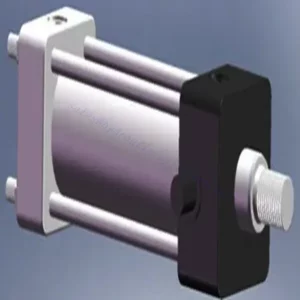
(1) Montage
Wir verfügen über eine erstklassige, unabhängige Forschungs- und Entwicklungsmontageplattform. Die Hydraulikzylinder-Produktionswerkstatt verfügt über vier halbautomatische Montagelinien für Hubzylinder und eine automatische Montagelinie für Kippzylinder mit einer geplanten jährlichen Produktionskapazität von 1 Million Stück. Die Spezialzylinderwerkstatt ist mit verschiedenen Spezifikationen eines halbautomatischen Reinigungsmontagesystems mit einer geplanten jährlichen Produktionskapazität von 200.000 ausgestattet und mit renommierten CNC-Bearbeitungsgeräten, einem Bearbeitungszentrum, einer hochpräzisen Spezialausrüstung für die Zylinderverarbeitung, einer Roboterschweißmaschine, einer automatischen Reinigungsmaschine, einer automatischen Zylindermontagemaschine und einer automatischen Lackierproduktionslinie ausgestattet. Es sind mehr als 300 Sets (Sätze) an kritischer Ausrüstung vorhanden. Die optimale Zuweisung und effiziente Nutzung der Ausrüstungsressourcen gewährleistet die Genauigkeitsanforderungen der Produkte und erfüllt die hohen Qualitätsanforderungen der Produkte.


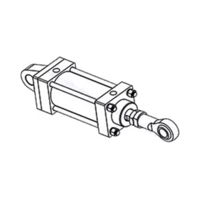
(2) Bearbeitungen
Die Bearbeitungswerkstatt ist mit einem maßgeschneiderten Schrägschienen-Drehzentrum, einem Bearbeitungszentrum, einer Hochgeschwindigkeits-Honmaschine, einem Schweißroboter und anderen zugehörigen Geräten ausgestattet, die die Bearbeitung von Zylinderrohren mit einem maximalen Innendurchmesser von 400 mm und einer maximalen Länge von 6 Metern ermöglichen.

(3) Schweißen

(4) Malerei und Beschichtung
Mit kleinen und mittleren Zylinder automatische Lackieranlagen auf Wasserbasis, zu erreichen automatische Roboter Be-und Entladen und automatische Spritzen, die Design-Kapazität von 4000 Stück pro Schicht;
Wir verfügen auch über eine halbautomatische Lackieranlage für große Zylinder, die von einer Energiekette angetrieben wird und eine Kapazität von 60 Kisten pro Schicht hat.


(5) Prüfung
Wir verfügen über erstklassige Prüfeinrichtungen und Prüfstände, um sicherzustellen, dass die Leistung des Zylinders den Anforderungen entspricht.

Wir sind einer der besten Hydraulikzylinderhersteller. Wir können umfassende Hydraulikzylinder anbieten. Wir bieten auch entsprechende landwirtschaftliche Getriebe. Wir haben unsere Produkte an Kunden weltweit exportiert und uns aufgrund unserer hervorragenden Produktqualität und unseres Kundendienstes einen guten Ruf erworben. Wir begrüßen Kunden im In- und Ausland, die uns kontaktieren, um Geschäfte zu verhandeln, Informationen auszutauschen und mit uns zusammenarbeiten!