30SD10-40 Magnet-Wegeventil
Als einer der Hersteller, Lieferanten und Exporteure von mechanischen Produkten, bieten wir Hydraulikzylinder und viele andere Produkte an.
Bitte setzen Sie sich mit uns in Verbindung, um Einzelheiten zu erfahren.
Post:sales@hydraulic-cylinders.net
Hersteller, Lieferant und Exporteur von Hydraulikzylindern.
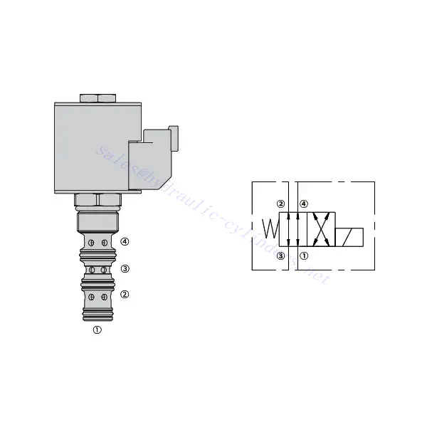
30SD10-40 Magnet-Wegeventil
Das Magnetwegeventil 30SD10-40 ist eine leistungsstarke Industriekomponente für die präzise und zuverlässige Steuerung von Flüssigkeiten in vielfältigen Anwendungen. Dank seiner fortschrittlichen Funktionen, der robusten Bauweise und des benutzerfreundlichen Designs bietet dieses Magnetwegeventil erhöhte Effizienz und Betriebssicherheit.
Das Magnetwegeventil 30SD10-40 ist eine zuverlässige und vielseitige Komponente, die eine präzise Fluidsteuerung in industriellen Anwendungen ermöglicht. Seine robuste Bauweise, die präzise Steuerung und die zuverlässige Leistung steigern Effizienz und Produktivität von Fluidsteuerungssystemen. Durch die Einhaltung der empfohlenen Anwendungsmethoden und Wartungsrichtlinien gewährleisten Sie optimale Leistung und Langlebigkeit des Magnetwegeventils 30SD10-40 in Ihren industriellen Prozessen.
30SD10-40 Magnet-Wegeventil – Eigenschaften:
- Robuste Konstruktion: Das Magnet-Wegeventil 30SD10-40 zeichnet sich durch hervorragende Verarbeitung und hochwertige Materialien aus und ist daher besonders langlebig. Dank seiner robusten Bauweise hält es auch anspruchsvollen Industrieumgebungen stand und bietet selbst unter rauen Bedingungen zuverlässige Leistung.
- Vielseitige Funktionalität: Dieses Magnet-Wegeventil bietet vielseitige Einsatzmöglichkeiten und eignet sich daher für ein breites Anwendungsspektrum. Es steuert effektiv die Strömungsrichtung von Flüssigkeiten und ermöglicht so einen präzisen und effizienten Betrieb in verschiedenen industriellen Systemen.
- Präzisionssteuerung: Das Magnet-Wegeventil 30SD10-40 bietet außergewöhnliche Präzision bei der Fluidsteuerung. Es ermöglicht die genaue Regelung und Einstellung von Fluidrichtung und -druck und gewährleistet so optimale Leistung und Effizienz in industriellen Prozessen.
- Zuverlässige Leistung: Dieses Magnet-Wegeventil bietet zuverlässige Leistung und minimiert das Risiko von Systemausfällen oder -unterbrechungen. Es arbeitet zuverlässig und trägt so zu höherer Produktivität und reduzierten Ausfallzeiten in industriellen Anlagen bei.
30SD10-40 Magnet-Wegeventil Parameter:
| Nenndruck | 207 bar (3000 psi) | |
| Spitzenfluss | 23 l/min (6 gpm) | |
| Flüssigkeit | Mineralische oder synthetische Stoffe mit Schmiereigenschaften | |
| Temperaturbereich ℃ | -54 bis 107 ℃ (Polyurethan-Dichtungen) | |
| -40 bis 100 °C (Buna N-Dichtungen) | ||
| -26 bis 204 ℃ (Fluorkohlenstoffdichtungen) | ||
| Viskositätsbereich | 7,4 bis 420 mm2/S | |
| Verschmutzungsgrad | Der Mindestverschmutzungsgrad beträgt ISO4406 Stufe 20/18/14, und Stufe 17/15/13 wird empfohlen, um die Lebensdauer zu verlängern | |
| Interne Leckage | ≤ 82 ml/min bei 207 bar | |
| Hohlraum | VC10-4 | |
| Spulenleistung | Kontinuierlich von 85% bis 115% Nennspannung | |
| Anfängliche Spulenstromaufnahme bei 20 °C | E-Spule | 1,7 A bei 12 VDC; 0,85 A bei 24 VDC |
| D-Spule | 1,67 A bei 12 VDC; 0,83 A bei 24 VDC | |
| Minimale Anzugsspannung | 85% mit einem Nenndruck von 207 bar | |
Vorteile des Magnet-Wegeventils 30SD10-40:
• Spule für Dauerbetrieb
• Die Kartuschen sind spannungsaustauschbar
• Optionale wasserdichte E-Spulen mit einer Schutzart bis IP69K
• Effiziente Nassarmaturkonstruktion
• Industriell üblicher Hohlraum
• Gehärtete Teile für lange Lebensdauer
Anwendungsmethode des Magnetwegeventils 30SD10-40 :
- Integration into the System: Integrate the 30SD10-40 Solenoid Directional Valve into the fluid control system following the manufacturer’s guidelines and specifications. Ensure proper alignment and connection between the valve and other system components to achieve optimal performance.
- Elektrischer Anschluss: Stellen Sie einen sicheren elektrischen Anschluss für das Magnetventil her. Beachten Sie den mitgelieferten Schaltplan und achten Sie auf die korrekte Polarität, um elektrische Störungen zu vermeiden. Beachten Sie beim Arbeiten mit elektrischen Anschlüssen die Sicherheitsrichtlinien.
- Steuerung der Fluidströmungsrichtung: Nutzen Sie das Magnetwegeventil, um die Fluidströmungsrichtung zu steuern. Das Ventil ist üblicherweise mit einem Hebel oder Stellantrieb zur manuellen Einstellung ausgestattet. Alternativ kann es zur Fernsteuerung in ein automatisiertes Steuerungssystem integriert werden.
- Pressure Adjustment: Use the solenoid directional valve to regulate fluid pressure within the system. Adjust the valve’s settings to achieve the desired pressure levels for optimal performance and efficiency.
Wie liest man Schaltpläne für Hydraulikventile?
Das Lesen von Schaltplänen für Hydraulikventile erfordert ein grundlegendes Verständnis der Hydrauliksymbole und ihrer Bedeutung. Die folgenden Schritte helfen Ihnen beim Lesen von Schaltplänen für Hydraulikventile:
- Machen Sie sich mit den Hydrauliksymbolen vertraut: Hydraulische Schaltpläne verwenden grafische Symbole zur Darstellung verschiedener Bauteile und Funktionen. Gängige Symbole sind Quadrate für Ventile, Linien für Rohre oder Schläuche, Pfeile für die Durchflussrichtung und Kreise für Druck- oder Durchflussregler. Machen Sie sich mit der Bedeutung dieser Symbole vertraut, bevor Sie fortfahren.
- Ventiltypen identifizieren: Suchen Sie in der schematischen Darstellung nach den Ventilsymbolen. Ventile können durch Quadrate unterschiedlicher Form und Ausrichtung dargestellt werden. Beispielsweise steht ein Quadrat mit einem diagonalen Strich für ein Rückschlagventil, während ein Quadrat mit einem Pfeil darin ein Wegeventil kennzeichnet.
- Bestimmen Sie die Ventilfunktion: Jedes Ventilsymbol kennzeichnet seine spezifische Funktion. Wegeventile bestimmen die Fließrichtung der Hydraulikflüssigkeit, Druckventile regeln den Druck. Durchflussventile steuern die Durchflussmenge, und Rückschlagventile lassen den Durchfluss nur in eine Richtung zu.
- Beachten Sie die Ventilanschlüsse: Beachten Sie die Linien oder Pfeile, die in das Ventilsymbol hinein- und herausführen. Diese Linien stellen die Fließwege der Hydraulikflüssigkeit dar. Pfeile zeigen die Fließrichtung an, und Linien, die Ventile und andere Komponenten verbinden, stellen die Verbindungen dar.
- Analysieren Sie die Ventilpositionen: Manche Schaltpläne für Hydraulikventile enthalten Symbole zur Veranschaulichung der Ventilstellungen. Diese Symbole stellen typischerweise den Ventilschieber oder Hebel in verschiedenen Positionen dar, z. B. geöffnet, geschlossen oder teilweise geöffnet. Das Verständnis der Ventilstellungen hilft Ihnen, die Durchflusswege und den Zustand des Hydrauliksystems zu bestimmen.
- Zusätzliche Symbole und Anmerkungen beachten: Hydraulische Schaltpläne können zusätzliche Symbole und Beschriftungen enthalten, die Manometer, Durchflussmesser, Filter, Druckspeicher oder andere Komponenten kennzeichnen. Machen Sie sich mit diesen Symbolen und ihrer Bedeutung vertraut, um ein umfassendes Verständnis des Systems zu erlangen.
- Folgen Sie den Flusspfaden: Verfolgen Sie die Strömungswege von der Hydraulikquelle durch die verschiedenen Ventile und Komponenten bis zum Aktor oder dem gewünschten Ausgang. Verstehen Sie, wie die Ventile zusammenwirken und wie sie Durchfluss, Druck und Richtung des Fluids steuern, um den gewünschten Systembetrieb zu gewährleisten.
- Siehe Legende oder Schlüssel: Der Schaltplan sollte eine Legende enthalten, die die Bedeutung jedes im Diagramm verwendeten Symbols erklärt. Sollten Sie auf unbekannte Symbole stoßen oder Zweifel an deren Bedeutung haben, konsultieren Sie bitte die Legende.
- Bei Bedarf weitere Ressourcen hinzuziehen: Wenn Sie ein tieferes Verständnis von Schaltplänen für Hydraulikventile benötigen, sollten Sie Hydrauliklehrbücher oder Online-Ressourcen konsultieren oder sich an Hydraulikexperten wenden, die Ihnen auf Ihre spezifischen Bedürfnisse zugeschnittene Anleitungen und Erklärungen geben können.
Fähigkeit und Kapazität der Fabrik:
(1) Montage
Wir verfügen über eine erstklassige, unabhängige Forschungs- und Entwicklungsmontageplattform. Die Hydraulikzylinder-Produktionswerkstatt verfügt über vier halbautomatische Montagelinien für Hubzylinder und eine automatische Montagelinie für Kippzylinder mit einer geplanten jährlichen Produktionskapazität von 1 Million Stück. Die Spezialzylinderwerkstatt ist mit verschiedenen Spezifikationen eines halbautomatischen Reinigungsmontagesystems mit einer geplanten jährlichen Produktionskapazität von 200.000 ausgestattet und mit renommierten CNC-Bearbeitungsgeräten, einem Bearbeitungszentrum, einer hochpräzisen Spezialausrüstung für die Zylinderverarbeitung, einer Roboterschweißmaschine, einer automatischen Reinigungsmaschine, einer automatischen Zylindermontagemaschine und einer automatischen Lackierproduktionslinie ausgestattet. Es sind mehr als 300 Sets (Sätze) an kritischer Ausrüstung vorhanden. Die optimale Zuweisung und effiziente Nutzung der Ausrüstungsressourcen gewährleistet die Genauigkeitsanforderungen der Produkte und erfüllt die hohen Qualitätsanforderungen der Produkte.


(2) Bearbeitungen
Die Bearbeitungswerkstatt ist mit einem maßgeschneiderten Schrägschienen-Drehzentrum, einem Bearbeitungszentrum, einer Hochgeschwindigkeits-Honmaschine, einem Schweißroboter und anderen zugehörigen Geräten ausgestattet, die die Bearbeitung von Zylinderrohren mit einem maximalen Innendurchmesser von 400 mm und einer maximalen Länge von 6 Metern ermöglichen.

(3) Schweißen

(4) Malerei und Beschichtung
Mit kleinen und mittleren Zylinder automatische Lackieranlagen auf Wasserbasis, zu erreichen automatische Roboter Be-und Entladen und automatische Spritzen, die Design-Kapazität von 4000 Stück pro Schicht;
Wir verfügen auch über eine halbautomatische Lackieranlage für große Zylinder, die von einer Energiekette angetrieben wird und eine Kapazität von 60 Kisten pro Schicht hat.


(5) Prüfung
Wir verfügen über erstklassige Prüfeinrichtungen und Prüfstände, um sicherzustellen, dass die Leistung des Zylinders den Anforderungen entspricht.

Wir sind einer der besten Hydraulikzylinderhersteller. Wir können umfassende Hydraulikzylinder anbieten. Wir bieten auch entsprechende landwirtschaftliche Getriebe. Wir haben unsere Produkte an Kunden weltweit exportiert und uns aufgrund unserer hervorragenden Produktqualität und unseres Kundendienstes einen guten Ruf erworben. Wir begrüßen Kunden im In- und Ausland, die uns kontaktieren, um Geschäfte zu verhandeln, Informationen auszutauschen und mit uns zusammenarbeiten!
Hydraulischer Zylinder Anwendung:
