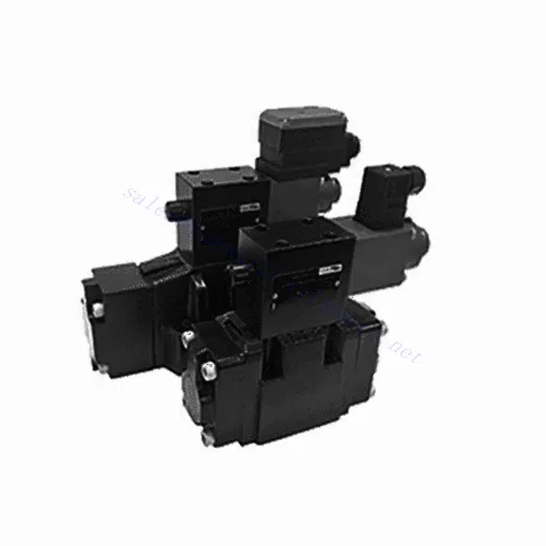
3DRE/M(E) Serie 3-Wege-Proportional-Druckreduzierventil mit Pilotsteuerung
Als einer der Hersteller, Lieferanten und Exporteure von mechanischen Produkten, bieten wir Hydraulikzylinder und viele andere Produkte an.
Bitte setzen Sie sich mit uns in Verbindung, um Einzelheiten zu erfahren.
Post:sales@hydraulic-cylinders.net
Hersteller, Lieferant und Exporteur von Hydraulikzylindern.
3DRE/M(E) Serie 3-Wege-Proportional-Druckreduzierventil mit Pilotsteuerung
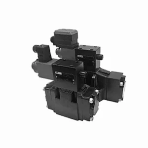
Das 3/2-Wege-Proportional-Druckminderungsventil der Serie 3DRE/M(E) ist eine hochmoderne Hydraulikkomponente für die präzise Druckregelung in Hydrauliksystemen. Dank seiner fortschrittlichen Proportional-Steuerungstechnologie gewährleistet dieses Ventil eine genaue Regelung, effiziente Leistung und zuverlässigen Betrieb.
Das 3-Wege-Proportional-Druckminderungsventil der Serie 3DRE/M(E) ermöglicht präzise Druckregelung, hohe Effizienz und zuverlässige Leistung in Hydrauliksystemen. Dank fortschrittlicher Proportionalregelung und 3-Wege-Konfiguration bietet dieses Ventil vielseitige Einsatzmöglichkeiten und Flexibilität bei der Druckregelung in verschiedenen Hydraulikkreisläufen. Durch die Einhaltung der empfohlenen Anwendungs- und Wartungsrichtlinien maximieren Sie die Vorteile und die Lebensdauer des Ventils der Serie 3DRE/M(E) und optimieren so die Druckregelung und die Gesamtleistung Ihres Hydrauliksystems. Rüsten Sie Ihre Hydraulikanlage noch heute auf und erleben Sie überlegene Druckregelung mit dem 3-Wege-Proportional-Druckminderungsventil der Serie 3DRE/M(E).
Hauptmerkmale des 3-Wege-Proportional-Druckminderungsventils der Serie 3DRE/M(E):
- Proportionale Druckregelung:
- Das Ventil der Serie 3DRE/M(E) bietet eine präzise und proportionale Druckregelung und ermöglicht die dynamische Anpassung der hydraulischen Druckniveaus.
- Diese Funktion gewährleistet eine präzise Druckregelung und hält einen gleichmäßigen und sicheren Druck im Hydrauliksystem aufrecht.
- Pilotbetriebenes Design:
- Durch die vorgesteuerte Konstruktion bietet das Ventil eine höhere Präzision und ein besseres Ansprechverhalten bei der Druckregelung.
- Es nutzt ein Pilotventil zur Modulation des Hauptventils, was präzise Einstellungen und eine verbesserte Kontrolle über die Druckreduzierung ermöglicht.
- 3-Wege-Konfiguration:
- Das Ventil der Serie 3DRE/M(E) zeichnet sich durch eine vielseitige 3-Wege-Konfiguration aus und bietet somit Flexibilität bei der Druckregelung in verschiedenen Hydraulikkreisläufen.
- Es ermöglicht die gleichzeitige Druckreduzierung in einem Kreislauf bei gleichzeitiger Druckversorgung eines anderen Kreislaufs.
- Effiziente Leistung:
- Durch den Einsatz fortschrittlicher Proportionalregelungstechnik gewährleistet das Ventil einen effizienten Betrieb, optimiert den Energieverbrauch und senkt die Betriebskosten.
- Es minimiert Druckschwankungen, verbessert die Systemeffizienz und trägt zur Gesamtproduktivität bei.
Parameter des 3-Wege-Proportional-Druckminderungsventils der Serie 3DRE/M(E):
| Hydraulisch | ||||||||
| Einbaulage | optional, vorzugsweise horizontal | |||||||
| Größe | 6 | 10 | ||||||
| Gewicht | 4WRA…L2X | Kg | 2 | 6.6 | ||||
| 4WRAE…L2X | 2.2 | 6.8 | ||||||
| Nenndurchfluss qnom, wenn Δp = 10 bar | L/min | 7, 15, 26 | 30, 60 | |||||
| Hysterese | % | ≤5 | ||||||
| Wiederholbarkeit | % | ≤1 | ||||||
| Ansprechsensitivität | % | ≤0,5 | ||||||
| Max. Betriebsdruck | Port s ABP | Bar | 315 | |||||
| Anschluss T | Bar | 210 | ||||||
| Flüssigkeit | Mineralöl geeignet für NBR- und FKM-Dichtungen | |||||||
| Phosphatester für FKM-Dichtung | ||||||||
| Flüssigkeitstemperaturbereich | 4WRA…L2X | ℃ | -20℃ bis 70℃ (-4°F bis 158°F) | |||||
| 4WRAE…L2X | ℃ | -20℃ bis 50℃ (-4° F bis 122° F) | ||||||
| Viskositätsbereich | mm²/s | 20 bis 380 (vorzugsweise 30 bis 46) | ||||||
| Verschmutzungsgrad | NAS1638 Klasse 9 oder ISO 4406 Klasse 20/18/15 | |||||||
| Elektrische Daten | ||||||||
| 1) Magnetspule | ||||||||
| Spannungstyp | Gleichstrom | |||||||
| Befehlswertsignal | ±10 V oder 4–20 mA | |||||||
| Maximalstrom pro Magnetspule | A | 2.5 | 1.5 | 0.8 | ||||
| Spulenwiderstand | Kältewert | Ω | 2 | 4.8 | 19.5 | |||
| Maximaler Warmwert | 3 | 7.2 | 28.8 | |||||
| Pflicht | % | ED100% | ||||||
| Spulentemperatur | ℃ | 150 | ||||||
| Ventilschutz nach EN 60529 | IP 65 | |||||||
| 2) Steuerelektronik | ||||||||
| Verstärker | 4WRA…L2X | VT-VSPA2-L2X | ||||||
| 4WRAE…L2X | Im Ventil integriert (OBE) | |||||||
| Betriebsspannung | Nennspannung | VDC | 24 | |||||
| Unterer Grenzwert | V | 21/22(4WRA), 19(4WRAE) | ||||||
| Oberer Grenzwert | V | 35 | ||||||
| Stromverbrauch des Verstärkers | Imax | A | <1,8 | |||||
| Imax | A | 3 | ||||||
Vorteile des 3-Wege-Proportional-Druckminderungsventils der Serie 3DREP(E):
• Das vorgesteuerte Überdruckventil dient der Druckreduzierung von P nach A und der Überlauffunktion von A nach T.
• Wird zur Montage der unteren Unterplatte verwendet und durch ein Proportionalmagnetventil angetrieben.
• Die Montagefläche entspricht DIN 24 340, Typ A, ISO 4401 und CETOP-RP 121H
• Der maximale Sicherheitsdruck kann ausgewählt werden.
• Spulenfederausrichtung
• 3DRE-Elektroniksteuerung: Verstärker nach europäischer Kartenspezifikation VT-VSPA1-1/VT-VSPD-1
• Bei Sollwert ist die Druckkennlinie linear
• Integrierter elektronischer Controller der Serie 3DRE(M)E
• Der durch einen Herstellungsfehler verursachte Sollwert – die Abweichung der Druckkennlinie ist gering
• Die Steigung des Druckanstiegs und -abfalls kann unabhängig eingestellt werden
Anwendungsmethode des 3-Wege-Proportional-Druckminderungsventils der Serie 3DREP(E).:
- Systembewertung:
- Analysieren Sie Ihr Hydrauliksystem und ermitteln Sie die spezifischen Druckregelungsanforderungen für jeden Kreislauf.
- Prüfen Sie anhand des Druckbereichs, der Durchflusskapazität und der Kompatibilität mit Ihrem System, ob das Ventil der Serie 3DRE/M(E) geeignet ist.
- Ventilauswahl:
- Wählen Sie die passende Variante des Ventils der Serie 3DRE/M(E) anhand Ihrer Systemparameter, des Druckbereichs und der Durchflussanforderungen.
- Berücksichtigen Sie die maximale Druckfestigkeit, die Ansprechzeit und die Betriebsbedingungen.
- Installation:
- Befolgen Sie die Installationsanweisungen des Herstellers sorgfältig und achten Sie auf die korrekte Ausrichtung und sichere Montage des Ventils.
- Schließen Sie das Ventil an das Hydrauliksystem an und achten Sie dabei auf leckagefreie Verbindungen und die korrekte Ausrichtung der Durchflussrichtung.
- Druckeinstellung:
- Nutzen Sie den mit dem Ventil der Serie 3DRE/M(E) mitgelieferten Pilotventil-Steuermechanismus, um den gewünschten Druckreduzierungsgrad für jeden Kreislauf einzustellen.
- Passen Sie die Steuerung des Pilotventils schrittweise an, um die gewünschte Druckregelung zu erreichen. Überwachen Sie dabei die Manometeranzeigen und die Systemreaktion.
Wie stellt man Hydraulikventile ein?
Das Einstellen von Hydraulikventilen ist eine entscheidende Aufgabe, um eine korrekte Durchflussregelung und Systemleistung in hydraulischen Anwendungen zu gewährleisten. Hier finden Sie eine Schritt-für-Schritt-Anleitung zum Einstellen von Hydraulikventilen:
- Identifizieren Sie das Ventil:
- Ermitteln Sie den Typ des Hydraulikventils, das Sie einstellen müssen: Druckbegrenzungsventil, Durchflussregelventil, Wegeventil oder ein anderer Typ.
- Suchen Sie das Ventil in Ihrem Hydrauliksystem. Es kann sich in der Nähe der Pumpe, im Steuerventilblock oder in bestimmten Hydraulikkomponenten befinden.
- Sammeln Sie die notwendigen Werkzeuge:
- Bevor Sie mit dem Einstellvorgang beginnen, legen Sie sich die benötigten Werkzeuge bereit, wie zum Beispiel einen verstellbaren Schraubenschlüssel, einen Schraubendreher, ein Manometer (falls erforderlich) und alle vom Ventilhersteller empfohlenen Spezialwerkzeuge.
- Die Funktion des Ventils verstehen:
- Machen Sie sich mit Zweck und Funktion des Ventils vertraut, das Sie einstellen möchten. Konsultieren Sie die technische Dokumentation des Ventils oder die Richtlinien des Herstellers für detaillierte Informationen.
- Die gewünschte Einstellung bestimmen:
- Ermitteln Sie die gewünschte Einstellung oder den Parameter, den Sie durch Verstellen des Ventils erreichen möchten. Dies kann der Druck, die Durchflussrate, die Richtung oder ein anderer einstellbarer Parameter je nach Ventiltyp sein.
- Vorprüfungen:
- Stellen Sie sicher, dass das Hydrauliksystem drucklos ist, bevor Sie Einstellungen vornehmen. Dies kann durch Abschalten des Systems und Ablassen des Restdrucks über geeignete Ventile erfolgen.
- Zugriff auf den Anpassungsmechanismus:
- Suchen Sie den Einstellmechanismus am Ventil. Je nach Ventiltyp kann es sich um eine Stellschraube, eine Kontermutter, einen Drehknopf oder ähnliche Vorrichtungen handeln.
- Bei manchen Ventilen muss unter Umständen eine Schutzkappe oder Abdeckung entfernt werden, um an den Einstellmechanismus zu gelangen.
- Nehmen Sie schrittweise Anpassungen vor:
- Nehmen Sie mithilfe des geeigneten Werkzeugs kleine, schrittweise Anpassungen am Ventil vor, um die gewünschte Einstellung zu erreichen.
- Beachten Sie die Anweisungen des Herstellers, um die Drehrichtung (im Uhrzeigersinn oder gegen den Uhrzeigersinn) und den erforderlichen Einstellbereich zu bestimmen.
- Nehmen Sie schrittweise Anpassungen vor und überprüfen Sie regelmäßig die Reaktion des Systems, um sicherzustellen, dass Sie sich in die gewünschte Richtung bewegen.
- Testen und Überwachen:
- Nach jeder Justierung muss das Hydrauliksystem aktiviert und seine Funktion überprüft werden.
- Verwenden Sie geeignete Messgeräte (Manometer, Durchflussmesser usw.), um zu überprüfen, ob das Ventil im gewünschten Bereich arbeitet.
- Überwachen Sie das System auf Anomalien oder unerwartetes Verhalten. Nehmen Sie gegebenenfalls weitere Anpassungen vor, um die Ventileinstellung zu optimieren.
- Einstellung sperren (falls zutreffend):
- Sobald Sie die gewünschte Einstellung erreicht haben, sichern Sie den Verstellmechanismus, um unbeabsichtigte Änderungen zu verhindern.
- Dies kann durch Anziehen einer Kontermutter, Sichern einer Stellschraube oder durch Anwendung einer anderen vom Ventilhersteller empfohlenen Methode erfolgen.
Fähigkeit und Kapazität der Fabrik:
(1) Montage
Wir verfügen über eine erstklassige, unabhängige Forschungs- und Entwicklungsmontageplattform. Die Hydraulikzylinder-Produktionswerkstatt verfügt über vier halbautomatische Montagelinien für Hubzylinder und eine automatische Montagelinie für Kippzylinder mit einer geplanten jährlichen Produktionskapazität von 1 Million Stück. Die Spezialzylinderwerkstatt ist mit verschiedenen Spezifikationen eines halbautomatischen Reinigungsmontagesystems mit einer geplanten jährlichen Produktionskapazität von 200.000 ausgestattet und mit renommierten CNC-Bearbeitungsgeräten, einem Bearbeitungszentrum, einer hochpräzisen Spezialausrüstung für die Zylinderverarbeitung, einer Roboterschweißmaschine, einer automatischen Reinigungsmaschine, einer automatischen Zylindermontagemaschine und einer automatischen Lackierproduktionslinie ausgestattet. Es sind mehr als 300 Sets (Sätze) an kritischer Ausrüstung vorhanden. Die optimale Zuweisung und effiziente Nutzung der Ausrüstungsressourcen gewährleistet die Genauigkeitsanforderungen der Produkte und erfüllt die hohen Qualitätsanforderungen der Produkte.


(2) Bearbeitungen
Die Bearbeitungswerkstatt ist mit einem maßgeschneiderten Schrägschienen-Drehzentrum, einem Bearbeitungszentrum, einer Hochgeschwindigkeits-Honmaschine, einem Schweißroboter und anderen zugehörigen Geräten ausgestattet, die die Bearbeitung von Zylinderrohren mit einem maximalen Innendurchmesser von 400 mm und einer maximalen Länge von 6 Metern ermöglichen.

(3) Schweißen

(4) Malerei und Beschichtung
Mit kleinen und mittleren Zylinder automatische Lackieranlagen auf Wasserbasis, zu erreichen automatische Roboter Be-und Entladen und automatische Spritzen, die Design-Kapazität von 4000 Stück pro Schicht;
Wir verfügen auch über eine halbautomatische Lackieranlage für große Zylinder, die von einer Energiekette angetrieben wird und eine Kapazität von 60 Kisten pro Schicht hat.


(5) Prüfung
Wir verfügen über erstklassige Prüfeinrichtungen und Prüfstände, um sicherzustellen, dass die Leistung des Zylinders den Anforderungen entspricht.

Wir sind einer der besten Hydraulikzylinderhersteller. Wir können umfassende Hydraulikzylinder anbieten. Wir bieten auch entsprechende landwirtschaftliche Getriebe. Wir haben unsere Produkte an Kunden weltweit exportiert und uns aufgrund unserer hervorragenden Produktqualität und unseres Kundendienstes einen guten Ruf erworben. Wir begrüßen Kunden im In- und Ausland, die uns kontaktieren, um Geschäfte zu verhandeln, Informationen auszutauschen und mit uns zusammenarbeiten!
Hydraulischer Zylinder Anwendung:
