DBETX Series Proportional Pressure Relief Hydraulic Valve
Als einer der Hersteller, Lieferanten und Exporteure von mechanischen Produkten, bieten wir Hydraulikzylinder und viele andere Produkte an.
Bitte setzen Sie sich mit uns in Verbindung, um Einzelheiten zu erfahren.
Post:sales@hydraulic-cylinders.net
Hersteller, Lieferant und Exporteur von Hydraulikzylindern.
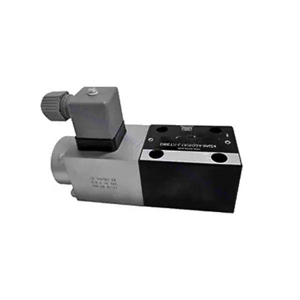
DBETX Series Proportional Pressure Relief Hydraulic Valve
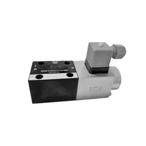
The DBETX series proportional pressure relief hydraulic valve is a versatile and high-performance hydraulic component designed to provide precise pressure relief in hydraulic systems. Engineered with advanced proportional control technology, this valve ensures optimal performance, efficiency, and safety.
The DBETX series proportional pressure relief hydraulic valve empowers hydraulic systems with precise pressure control, enhanced efficiency, and equipment protection. With its proportional pressure relief capabilities, this valve ensures optimal performance across a wide range of applications. By following the recommended usage methods and maintenance guidelines, you can maximize the benefits and reliability of the DBETX series valve, elevating the performance and control of your hydraulic system. Upgrade your hydraulic setup today and experience superior pressure regulation with the DBETX series proportional pressure relief hydraulic valve.
DBETX Series Proportional Pressure Relief Hydraulic Valve Key Characteristics:
- Proportional Pressure Relief:
- The DBETX series valve delivers proportional pressure relief, allowing for accurate and dynamic hydraulic pressure control.
- It ensures precise pressure regulation in response to varying load conditions, preventing damage to hydraulic components and optimizing system performance.
- Verbesserte Systemeffizienz:
- This valve enables precise control of hydraulic flow rates, resulting in enhanced system efficiency and reduced energy consumption.
- Maintaining the desired pressure levels minimizes pressure fluctuations, enhances overall productivity, and reduces operational costs.
- Safety and Equipment Protection:
- The DBETX series valve acts as a safeguard by limiting the pressure within the hydraulic system, protecting equipment and operators from potential damage or accidents.
- It prevents overloading and ensures the longevity of hydraulic components, reducing the risk of system failures and downtime.
- Breites Anwendungsspektrum:
- With its versatile design and compatibility with various hydraulic systems, the DBETX series valve can be used in a wide range of applications across industries such as manufacturing, construction, agriculture, and more.
- It offers flexibility and adaptability, making it suitable for diverse hydraulic setups and requirements.
DBETX Series Proportional Pressure Relief Hydraulic Valve Parameter:
| Allgemein | ||||||
| Konstruktion | Poppet valve, direct drive | |||||
| Betätigung | Proportionalmagnet ohne Positionsregelung, externer Verstärker | |||||
| Anschlussart | Subplate, mounting hole configuration NG6 (ISO 4401-03-02-0-94) | |||||
| Einbaulage | Optional | |||||
| Umstände Temperaturbereich | ℃ | -20…+50 | ||||
| Gewicht | Kg | about 2.1 | ||||
| Vibrationsfestigkeit, Prüfbedingungen | Max. 25 g, shaken in 3 dimensions(24 h) | |||||
| Hydraulic (measured with HLP 46, Voil=40℃±5℃) | ||||||
| Druckflüssigkeit | Hydrauliköl nach DIN 51524…535, andere Flüssigkeiten nach vorheriger Absprache | |||||
| Viskositätsbereich | empfohlen | 20…100 | ||||
| max. zulässig | 10…800 | |||||
| Druckflüssigkeitstemperaturbereich | ℃ | -20…+80 | ||||
| Maximum permitted degree of contamination of pressure fluid Purity class to ISO 4406(c) | Klasse 18/16/13 | |||||
| Strömungsrichtung | Siehe Symbol | |||||
| Max. setting pressure (Q = 1 l/min) | Bar | 50 | 80 | 180 | 250 | 315 |
| Min. settable pressure (Q = 1 l/min) | Bar | 2 | 3 | 4 | 5 | 8 |
| Max. operating pressure(Q = 1 l/min) | Bar | Port P: 315 | ||||
| Max. Druck | Bar | Port T: 250 | ||||
| Max. mechanical pressure limitation level, e.g. when solenoid current I>Imax | Bar | <55 | <85 | <186 | <258 | <325 |
| Statisch/Dynamisch | ||||||
| Hysterese | % | ≤4 | ||||
| Response time 100% signal changen | MS | On<60 / Off<70 | ||||
| Inversionsbereich | % | ≤3 | ||||
| Elektrische Daten | ||||||
| Faktor der Zyklusdauer | % | 100 ED | ||||
| Schutzart | IP 65 nach DIN 40050 und IEC 14434/5 | |||||
| Magnetventilanschluss | Plug-in connector to DIN EN 175301-803/ISO 4400 | |||||
| Leistung | 24VDCnom | |||||
DBETX Series Proportional Pressure Relief Hydraulic Valve Advantages:
• Direkt, um den Systemdruck zu begrenzen
• Can adjust pressure by controlling the current with the solenoid according to the characteristic curve
• In the event of electrical failure, the restricted pressure is still within safety level (solenoid current > Imax)
• External amplifying sub-plate mounting has slope and valve calibration functions (separate order)
Usage Method Of DBETX Series Proportional Pressure Relief Hydraulic Valve:
- Systembewertung:
- Evaluate your hydraulic system and identify the specific requirements for pressure control and relief.
- Determine if the DBETX series valve is compatible with your system and suitable for your application based on its pressure range, flow capacity, and other specifications.
- Ventilauswahl:
- Choose the appropriate DBETX series valve variant based on your system parameters, pressure range, and flow requirements.
- Berücksichtigen Sie die maximale Druckfestigkeit, die Ansprechzeit und die Betriebsbedingungen.
- Installation:
- Befolgen Sie die Installationsanweisungen des Herstellers sorgfältig und achten Sie auf die korrekte Ausrichtung und sichere Montage des Ventils.
- Schließen Sie das Ventil an das Hydrauliksystem an und achten Sie dabei auf leckagefreie Verbindungen und die korrekte Ausrichtung der Durchflussrichtung.
- Druckeinstellung:
- Adjust the pressure relief setting on the DBETX series valve to match the desired pressure range for your application.
- Utilize the proportional control signals or adjustment mechanisms provided with the valve to achieve precise pressure regulation.
How To Adjust A Hydraulic Pressure Relief Valve?
Adjusting a hydraulic pressure relief valve allows you to set the desired maximum pressure in a hydraulic system. This is important for maintaining system integrity and preventing damage to components. Here’s a step-by-step guide on how to adjust a hydraulic pressure relief valve:
- Identify the Pressure Relief Valve:
- Locate the pressure relief valve in your hydraulic system. It is typically installed in the hydraulic line and often near the pump or control valve.
- Understand the Valve Design:
- Familiarize yourself with the specific design of the pressure relief valve you are working with. Different valves may have varying adjustment mechanisms, such as a knob, screw, or locknut.
- Determine the Desired Pressure:
- Assess the requirements of your hydraulic system and determine the desired maximum pressure. This will guide you in adjusting the pressure relief valve accurately.
- Bereiten Sie das System vor:
- Before making any adjustments, shut off the hydraulic system and relieve the pressure by moving the control levers back and forth or following the manufacturer’s recommended procedure.
- Locate the Adjustment Mechanism:
- Identify the adjustment mechanism on the pressure relief valve. It could be a knob, screw, or locknut positioned on the valve body or adjacent to it.
- Adjust the Valve:
- If the valve has a knob or handle, turn it clockwise to increase the pressure relief setting or counterclockwise to decrease it. If the valve has a screw, turn it clockwise to increase the pressure relief or counterclockwise to decrease it.
- Nehmen Sie schrittweise Anpassungen vor:
- When adjusting the pressure relief valve, make small, incremental changes to avoid sudden or drastic variations in pressure. This allows you to fine-tune the maximum pressure and achieve the desired performance.
- Observe the System:
- With each adjustment, observe the hydraulic system and its components. Pay attention to the pressure gauge readings to see if they align with the desired maximum pressure.
- Testen und Überprüfen:
- Operate the hydraulic system and monitor the pressure to ensure that it remains within the desired range. Check for any pressure fluctuations or irregularities that may indicate the need for further adjustment.
- Lock the Adjustment:
- Once you have achieved the desired pressure relief setting, secure the adjustment mechanism to prevent unintended changes. Some valves may have a locking nut or set screw that can be tightened to hold the adjustment in place.
- Monitor and Revisit:
- Regularly monitor the pressure relief valve and the hydraulic system. If there are changes in the system or if the desired maximum pressure needs to be adjusted, revisit the pressure relief valve and repeat the adjustment process as needed.
Fähigkeit und Kapazität der Fabrik:
(1) Montage
Wir verfügen über eine erstklassige, unabhängige Forschungs- und Entwicklungsmontageplattform. Die Hydraulikzylinder-Produktionswerkstatt verfügt über vier halbautomatische Montagelinien für Hubzylinder und eine automatische Montagelinie für Kippzylinder mit einer geplanten jährlichen Produktionskapazität von 1 Million Stück. Die Spezialzylinderwerkstatt ist mit verschiedenen Spezifikationen eines halbautomatischen Reinigungsmontagesystems mit einer geplanten jährlichen Produktionskapazität von 200.000 ausgestattet und mit renommierten CNC-Bearbeitungsgeräten, einem Bearbeitungszentrum, einer hochpräzisen Spezialausrüstung für die Zylinderverarbeitung, einer Roboterschweißmaschine, einer automatischen Reinigungsmaschine, einer automatischen Zylindermontagemaschine und einer automatischen Lackierproduktionslinie ausgestattet. Es sind mehr als 300 Sets (Sätze) an kritischer Ausrüstung vorhanden. Die optimale Zuweisung und effiziente Nutzung der Ausrüstungsressourcen gewährleistet die Genauigkeitsanforderungen der Produkte und erfüllt die hohen Qualitätsanforderungen der Produkte.


(2) Bearbeitungen
Die Bearbeitungswerkstatt ist mit einem maßgeschneiderten Schrägschienen-Drehzentrum, einem Bearbeitungszentrum, einer Hochgeschwindigkeits-Honmaschine, einem Schweißroboter und anderen zugehörigen Geräten ausgestattet, die die Bearbeitung von Zylinderrohren mit einem maximalen Innendurchmesser von 400 mm und einer maximalen Länge von 6 Metern ermöglichen.

(3) Schweißen

(4) Malerei und Beschichtung
Mit kleinen und mittleren Zylinder automatische Lackieranlagen auf Wasserbasis, zu erreichen automatische Roboter Be-und Entladen und automatische Spritzen, die Design-Kapazität von 4000 Stück pro Schicht;
Wir verfügen auch über eine halbautomatische Lackieranlage für große Zylinder, die von einer Energiekette angetrieben wird und eine Kapazität von 60 Kisten pro Schicht hat.


(5) Prüfung
Wir verfügen über erstklassige Prüfeinrichtungen und Prüfstände, um sicherzustellen, dass die Leistung des Zylinders den Anforderungen entspricht.

Wir sind einer der besten Hydraulikzylinderhersteller. Wir können umfassende Hydraulikzylinder anbieten. Wir bieten auch entsprechende landwirtschaftliche Getriebe. Wir haben unsere Produkte an Kunden weltweit exportiert und uns aufgrund unserer hervorragenden Produktqualität und unseres Kundendienstes einen guten Ruf erworben. Wir begrüßen Kunden im In- und Ausland, die uns kontaktieren, um Geschäfte zu verhandeln, Informationen auszutauschen und mit uns zusammenarbeiten!
Hydraulischer Zylinder Anwendung:
