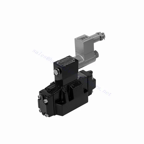
GWEH Series Explosion-proof Directional Hydraulic Valve
Als einer der Hersteller, Lieferanten und Exporteure von mechanischen Produkten, bieten wir Hydraulikzylinder und viele andere Produkte an.
Bitte setzen Sie sich mit uns in Verbindung, um Einzelheiten zu erfahren.
Post:sales@hydraulic-cylinders.net
Hersteller, Lieferant und Exporteur von Hydraulikzylindern.
GWEH Series Explosion-proof Directional Hydraulic Valve
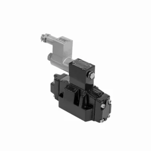
The GWEH series explosion-proof directional hydraulic valve is an innovative solution designed to provide optimal safety and precise control in hydraulic systems operating in hazardous environments. With its explosion-proof features, reliable performance, and advanced functionalities, this valve offers enhanced safety measures, efficient fluid flow control, and compatibility with various industrial applications.
The GWEH series explosion-proof directional hydraulic valve is a reliable and efficient solution for industries operating in hazardous environments. With its explosion-proof design, precise directional control, versatility, and high performance, this valve ensures safety and control in hydraulic systems. Following the recommended usage methods and adhering to regular maintenance practices, the GWEH series valve delivers safe and efficient operation in explosive atmospheres. Upgrade your hydraulic system with the GWEH series explosion-proof directional hydraulic valve and experience enhanced safety, optimal fluid flow control, and reliable performance.
GWEH Series Explosion-proof Directional Hydraulic Valve Key Characteristics:
- Explosionsgeschützte Ausführung:
- The GWEH series valve is engineered with a robust explosion-proof design, ensuring safe operation in environments containing flammable gases or dust.
- It complies with stringent safety standards and certifications, minimizing the risk of ignition and ensuring the safety of personnel and equipment.
- Richtungssteuerung:
- This hydraulic valve provides precise directional control of fluid flow, allowing for the activation and deactivation of specific hydraulic actuators.
- It enables smooth and reliable operation of various hydraulic functions, such as cylinder extension and retraction or motor direction changes.
- Vielseitigkeit und Kompatibilität:
- The GWEH series valve is highly versatile and compatible with various hydraulic systems and applications.
- It can seamlessly integrate into industrial machinery, mobile equipment, and automation systems operating in hazardous environments.
- Hohe Leistung:
- With its advanced design and high-quality construction, the GWEH series hydraulic valve delivers exceptional performance and reliability.
- It ensures consistent and precise control over fluid flow, contributing to efficient and optimized system operation.
GWEH Series Explosion-proof Directional Hydraulic Valve Parameter:
NG10
| Working pressureP,A,B | Bar | 315 | |||||||||
| Anschluss T | With external pilot oil drain | Bar | 315 | ||||||||
| With internal pilot oil drain | Bar | 210 | |||||||||
| Anschluss Y | With external pilot oil drain | Bar | 210 | ||||||||
| Min. Steuerdruck | Mit externer Steuerölversorgung
Mit interner Steuerölversorgung (not apply to C, Z, F, G, H, P, T, V) |
Bar | 3-position valve 10 | ||||||||
| Spring-return 2-position valve 10 | |||||||||||
| Hydraulic-return 2-position valve 7 | |||||||||||
| Mit interner Steuerölversorgung ( apply to C, Z, F, G, H, P, T, V) |
Bar | 4.5 | |||||||||
| Max. control pressure | Bar | 250 | |||||||||
| Flüssigkeit | Mineralöl, Phosphatester | ||||||||||
| Flüssigkeitstemperaturbereich | ℃ | -30 bis +80 ( NBR-Dichtungen | |||||||||
| -20 bis +80 (FKM-Dichtungen) | |||||||||||
| Viskositätsbereich | mm2/S | 2,8 bis 500 | |||||||||
| Controlled quantity in commutating process | cm3 | 3-position valve 2.04 2-position valve 4.08 | |||||||||
| Switching times (= Valve switching time from the neutral position to the switched position)(DC ) | |||||||||||
| Control pressure | Bar | 70 | 140 | 210 | 250 | ||||||
| 3-position valve | MS | 65 | 60 | 55 | 50 | ||||||
| 2-position valve | MS | 80 | 75 | 70 | 65 | ||||||
| Schaltzeiten (= Schaltzeit des Ventils von der Schaltstellung in die Neutralstellung) | |||||||||||
| 3-position valve | MS | 30 | |||||||||
| 2-position valve | MS | 35 | 40 | 30 | 35 | 25 | 30 | 20 | 25 | ||
| Flow of shortest switching time | L/min | etwa 35 | |||||||||
| Einbaulage | HC, HD, HK, HZ and HY of hydraulic return shall be installed horizontally. The rest are arbitrary | ||||||||||
NG16
| Technische Daten | G-..WEH16../6B2.. type | |||||||
| Working pressureP,A,B bar | 350 | |||||||
| Anschluss T | Mit externer Steuerölablassstange | 250 | ||||||
| Mit interner Steueröl-Ablassstange | 210 | |||||||
| Hydraulic-centering 3-position valve With internal pilot oil drain is impossible | ||||||||
| Anschluss Y | Mit externer Steuerölablassstange | 210 | ||||||
| Min. Steuerdruck | With external pilot oil supply bar
With internal pilot oil supply bar |
3-position valve 14 | ||||||
| Federrückgestelltes 2-Positionen-Ventil 14 | ||||||||
| Hydraulic-return 2-position valve 14 | ||||||||
| Mit interner Steuerölversorgung ( apply to C、Z、F、G、H、P、T、V) bar |
When applying back pressure valve or the flow is large, enginery of spool valve is 4.5 bar as C、Z、F、G、H、P、T and V | |||||||
| Max. Steuerdruck bar | 250 | |||||||
| Flüssigkeit | Mineralöl, Phosphatester | |||||||
| Flüssigkeitstemperaturbereich ℃ | -30 bis +80 ( NBR-Dichtungen | |||||||
| -20 bis +80 (FKM-Dichtungen) | ||||||||
| Viscosity range mm2 /s 2 | 2,8 bis 500 | |||||||
| Schaltsteuerölmenge | ||||||||
| -Spring-centering 3-position valve cm3 | 5.72 | |||||||
| -2-position valve cm3 | 11.45 | |||||||
| * Schaltzeiten (= Ventilschaltzeit von der Neutralstellung in die Schaltstellung) (AC und DC) | ||||||||
| Steuerdruck bar | 50 | 150 | 250 | |||||
| – Spring-centering 3-position valve ms | 65 | 60 | 58 | |||||
| – 2-position valve ms | 65 | 55 | 50 | |||||
| *Schaltzeiten (= Ventilschaltzeit von der Neutralstellung in die Schaltstellung) | ||||||||
| – Spring-centering 3-position valve ms | 40 | |||||||
| – 2-position valve ms | 45 | 35 | 30 | |||||
| Einbaulage | C,D,K,Z,Y Type hydraulic-return valves are installed horizontally, the rest can be installed arbitrarily。 | |||||||
| Flow of shorter switching time L/min | etwa 35 | |||||||
| Weight of the valve kg | about 10.6 | |||||||
NG25
| Technische Daten | G-H-…WEH25../6B2… type | |||||||||
| Working pressureP,A,B bar | 350 | |||||||||
| Anschluss T | Mit externer Steuerölablassstange | 250 | ||||||||
| Mit interner Steueröl-Ablassstange | 210 | |||||||||
| Hydraulic-centering 3-position valve With internal pilot oil drain is impossible | ||||||||||
| Anschluss Y | Mit externer Steuerölablassstange | 210 | ||||||||
| Min. Steuerdruck | With external pilot oil supply bar
With internal pilot oil supply bar |
Spring-centering 3-position valve 13 | ||||||||
| Hydraulic-centering 3-position valve 18 | ||||||||||
| Spring-return 2-position valve 13 | ||||||||||
| Hydraulic-return 2-position valve 18 | ||||||||||
| Mit interner Steuerölversorgung | When applying back pressure valve or the flow is large, enginery of spool valve is 4.5 bar as C、Z、F、G、H、P、T and V | |||||||||
| Max. Steuerdruck bar | 250 | |||||||||
| Flüssigkeit | Mineralöl, Phosphatester | |||||||||
| Flüssigkeitstemperaturbereich ℃ | -30 bis +80 ( NBR-Dichtungen | |||||||||
| -20 bis +80 (FKM-Dichtungen) | ||||||||||
| Viscosity range mm2 /s 2 | 2,8 bis 500 | |||||||||
| Schaltsteuerölmenge | ||||||||||
| -Spring-centering 3-position valve cm3 | 14.2 | |||||||||
| -2-position valve cm3 | 28.4 | |||||||||
| * Schaltzeiten (= Ventilschaltzeit von der Neutralstellung in die Schaltstellung) (AC und DC) | ||||||||||
| Steuerdruck bar | 50 | 140 | 210 | 250 | ||||||
| – Spring-centering 3-position valve ms | 85 | 75 | 70 | 65 | ||||||
| – 2-position valve ms | 160 | 130 | 120 | 105 | ||||||
| **Schaltzeiten (= Ventilschaltzeit von der Neutralstellung in die Schaltstellung) | ||||||||||
| – Spring-centering 3-position valve ms | 40 | |||||||||
| – 2-position valve ms | 125 | 100 | 90 | 80 | ||||||
| Einbaulage | C,D,K,Z,Y Type hydraulic-return valves are installed horizontally, the rest can be installed arbitrarily。 | |||||||||
| Flow of shorter switching time L/min | etwa 35 | |||||||||
| Weight of the valve kg | about 19 | |||||||||
GWEH Series Explosion-proof Directional Hydraulic Valve Advantages:
• Directional valve directional the oil path by controlling the main spool
• WEH elektrohydraulische Steuerung
• Two-position four-way or three-position four-way
• Installation face follows DIN 24340 A, ISO 4401, and CETOP-RP 121H Sub-plate mounting connection
• Spule ersetzen, ohne Öl freizusetzen
Usage Method Of GWEH Series Explosion-proof Directional Hydraulic Valve :
- Bewertung von Gefahrenbereichen:
- Führen Sie eine gründliche Bewertung des Gefahrenbereichs durch, um die spezifischen Explosionsschutzanforderungen und die Klassifizierung zu ermitteln.
- Bestimmen Sie die geeigneten Sicherheitsmaßnahmen und Vorkehrungen, die zur Einhaltung der Vorschriften erforderlich sind.
- Ventilauswahl:
- Select the GWEH Series Valve with the suitable specifications, considering factors such as pressure ratings, flow capacity, and voltage requirements.
- Stellen Sie die Kompatibilität mit dem Hydrauliksystem und der spezifischen Gefahrenumgebung sicher.
- Installation:
- Follow the manufacturer’s instructions for proper installation of the GWEH Series Valve in the hydraulic system.
- Sorgen Sie für eine sichere Montage und ordnungsgemäße elektrische Anschlüsse und halten Sie sich dabei an die empfohlenen Drehmomentwerte und Verdrahtungsrichtlinien.
- Steuerung und Aktivierung:
- Utilize the recommended control method, such as electrical signals or remote activation, to operate the GWEH Series Valve.
- Schließen Sie das Ventil gemäß den bereitgestellten Schaltplänen an eine geeignete Stromquelle und ein geeignetes Steuerungssystem an.
How Does A Hydraulic Control Valve Work?
A hydraulic control valve is a critical component in hydraulic systems that regulates the flow and direction of hydraulic fluid to control the operation of hydraulic actuators. It enables precise control over various hydraulic functions, such as extending or retracting cylinders, controlling motor speed and direction, or adjusting the flow rate of hydraulic fluid. Here’s an overview of how a hydraulic control valve works:
- Ventilstruktur:
- A hydraulic control valve typically consists of a valve body, spools or poppets, and various internal passages.
- The valve body contains inlet and outlet ports for fluid connection and chambers that direct the flow.
- The spools or poppets are movable elements within the valve body that control the flow paths and connect the appropriate ports.
- Durchflusssteuerung:
- The hydraulic control valve regulates the flow of hydraulic fluid by opening and closing specific flow paths within the valve.
- The position of the spools or poppets determines which ports are connected and allows fluid to flow in the desired direction.
- Richtungssteuerung:
- Hydraulic control valves provide directional control by selectively connecting or blocking fluid flow to different hydraulic actuators.
- By adjusting the position of the spools or poppets, the valve determines which actuator receives fluid and in which direction it moves.
- Actuation Methods:
- Hydraulic control valves can be actuated using manual levers, mechanical linkages, solenoids, or pilot pressure control.
- Manual control valves are operated by moving the levers or handles to position the spools or poppets.
- Solenoid-controlled valves use electromagnetic coils to actuate the valve, allowing for remote or automated control.
- Control Modes:
- Hydraulic control valves offer different control modes, such as 2-way, 3-way, or 4-way control.
- A 2-way control valve controls flow in one direction, allowing or blocking fluid flow.
- A 3-way control valve has three ports and can control the flow between two ports while blocking the third.
- A 4-way control valve has four ports and can route fluid between two actuator ports while blocking the other two.
- Druckausgleich:
- Some hydraulic control valves are equipped with pressure compensation features to maintain a consistent flow rate despite changes in system pressure.
- These valves adjust the flow passages based on pressure differentials, allowing for precise control regardless of varying operating conditions.
- Feedback and Control Loops:
- Advanced hydraulic control valves may incorporate feedback mechanisms, such as position or pressure sensors, to provide feedback to a control system.
- This feedback enables closed-loop control, where the system can monitor and adjust the valve’s position or flow based on desired setpoints or operating conditions.
Fähigkeit und Kapazität der Fabrik:
(1) Montage
Wir verfügen über eine erstklassige, unabhängige Forschungs- und Entwicklungsmontageplattform. Die Hydraulikzylinder-Produktionswerkstatt verfügt über vier halbautomatische Montagelinien für Hubzylinder und eine automatische Montagelinie für Kippzylinder mit einer geplanten jährlichen Produktionskapazität von 1 Million Stück. Die Spezialzylinderwerkstatt ist mit verschiedenen Spezifikationen eines halbautomatischen Reinigungsmontagesystems mit einer geplanten jährlichen Produktionskapazität von 200.000 ausgestattet und mit renommierten CNC-Bearbeitungsgeräten, einem Bearbeitungszentrum, einer hochpräzisen Spezialausrüstung für die Zylinderverarbeitung, einer Roboterschweißmaschine, einer automatischen Reinigungsmaschine, einer automatischen Zylindermontagemaschine und einer automatischen Lackierproduktionslinie ausgestattet. Es sind mehr als 300 Sets (Sätze) an kritischer Ausrüstung vorhanden. Die optimale Zuweisung und effiziente Nutzung der Ausrüstungsressourcen gewährleistet die Genauigkeitsanforderungen der Produkte und erfüllt die hohen Qualitätsanforderungen der Produkte.


(2) Bearbeitungen
Die Bearbeitungswerkstatt ist mit einem maßgeschneiderten Schrägschienen-Drehzentrum, einem Bearbeitungszentrum, einer Hochgeschwindigkeits-Honmaschine, einem Schweißroboter und anderen zugehörigen Geräten ausgestattet, die die Bearbeitung von Zylinderrohren mit einem maximalen Innendurchmesser von 400 mm und einer maximalen Länge von 6 Metern ermöglichen.

(3) Schweißen

(4) Malerei und Beschichtung
Mit kleinen und mittleren Zylinder automatische Lackieranlagen auf Wasserbasis, zu erreichen automatische Roboter Be-und Entladen und automatische Spritzen, die Design-Kapazität von 4000 Stück pro Schicht;
Wir verfügen auch über eine halbautomatische Lackieranlage für große Zylinder, die von einer Energiekette angetrieben wird und eine Kapazität von 60 Kisten pro Schicht hat.


(5) Prüfung
Wir verfügen über erstklassige Prüfeinrichtungen und Prüfstände, um sicherzustellen, dass die Leistung des Zylinders den Anforderungen entspricht.

Wir sind einer der besten Hydraulikzylinderhersteller. Wir können umfassende Hydraulikzylinder anbieten. Wir bieten auch entsprechende landwirtschaftliche Getriebe. Wir haben unsere Produkte an Kunden weltweit exportiert und uns aufgrund unserer hervorragenden Produktqualität und unseres Kundendienstes einen guten Ruf erworben. Wir begrüßen Kunden im In- und Ausland, die uns kontaktieren, um Geschäfte zu verhandeln, Informationen auszutauschen und mit uns zusammenarbeiten!
Hydraulischer Zylinder Anwendung:
