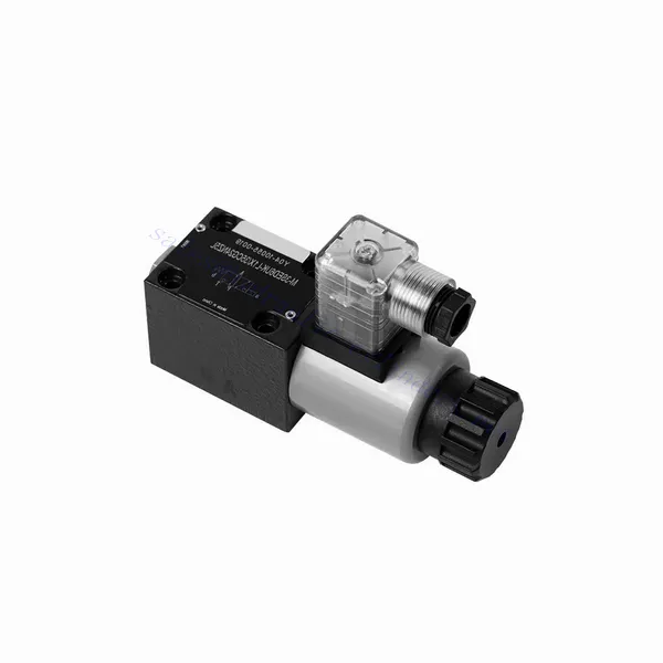
M-SED Series Directional Poppet Hydraulic Valve With Solenoid Actuation
M-SED Series Directional Poppet Hydraulic Valve With Solenoid Actuation
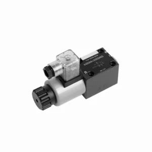
The M-SED series directional poppet hydraulic valve with solenoid actuation is a cutting-edge solution that provides precise control and optimal efficiency in hydraulic systems. With its innovative design, reliable performance, and advanced solenoid actuation, this valve offers enhanced fluid flow control, flexibility, and compatibility with various industrial applications.
The M-SED series directional poppet hydraulic valve with solenoid actuation is a reliable and efficient solution for hydraulic systems. With its directional poppet design, advanced solenoid actuation, versatility, and high flow capacity, this valve offers precise control, enhanced efficiency, and compatibility with various applications. The M-SED series valve delivers optimal performance and reliability by following the recommended usage methods and adhering to regular maintenance practices. Upgrade your hydraulic system with the M-SED series directional poppet hydraulic valve and experience enhanced control, efficiency, and productivity.
M-SED Series Directional Poppet Hydraulic Valve With Solenoid Actuation Key Characteristics:
- Directional Poppet Design:
- The M-SED series valve features a directional poppet design, ensuring reliable and efficient fluid flow control.
- It allows for quick response times and precise regulation of fluid direction, enhancing overall system performance.
- Ενεργοποίηση ηλεκτρομαγνητικής βαλβίδας:
- This hydraulic valve is equipped with advanced solenoid actuation and provides remote and automated control capabilities.
- The solenoid allows quick and accurate switching between different flow paths, improving operational efficiency.
- Ευελιξία και Συμβατότητα:
- The M-SED series valve is highly versatile and compatible with various hydraulic systems and applications.
- It can be seamlessly integrated into industrial machinery, mobile equipment, and automation systems, enhancing performance.
- Υψηλή χωρητικότητα ροής:
- With its robust design and optimized flow paths, the M-SED series valve offers high flow capacity.
- It ensures efficient fluid transfer, reducing pressure drops and maximizing system throughput.
M-SED Series Directional Poppet Hydraulic Valve With Solenoid Actuation Parameter:
| Προδιαγραφές | NG6 | NG10 | ||
| Θέση εγκατάστασης | Προαιρετικός | |||
| Environment temperature | ℃ | -30 έως +50 (σφραγίδες NBR) | ||
| -20 έως +50 (σφραγίδες FKM) | ||||
| Βάρος | Two three-way solenoidic directional valve | Κιλά | 1.5 | 2.6 |
| Two four-way solenoidic directional valve | Κιλά | 2.3 | 3.9 | |
| Μέγιστη λειτουργούσα πίεση | μπαρ | 350 | 350 | |
| Μέγιστος ρυθμός ροής | Λ/λεπτό | 25 | 40 | |
| Υγρό | Ορυκτέλαιο κατάλληλο για στεγανοποίηση NBR και FKM | |||
| Φωσφορικός εστέρας για σφράγιση FKM | ||||
| Εύρος θερμοκρασίας ρευστού | ℃ | -30 έως +80 (σφραγίδες NBR) | ||
| -20 έως +80 (σφραγίδες FKM) | ||||
| Εύρος ιξώδους | χιλ.2/μικρό | 2,8 έως 500 | ||
| Βαθμός μόλυνσης | Maximum permissible degree of fluid contamination: Class 9. NAS 1638 | Μέγιστος επιτρεπόμενος βαθμός μόλυνσης υγρού: Κλάση 9. NAS 1638 ή 20/18/15, ISO4406 | ||
M-SED Series Directional Poppet Hydraulic Valve With Solenoid Actuation Advantages:
• Direct solenoid shutoff valve
• Installation face follow DIN 24340 A, ISO 4401 and CETOP-RP 121H
• No leak
• Responsive switching under high pressure
• Η αντικατάσταση του πηνίου δεν απαιτεί το άνοιγμα του σφραγισμένου θαλάμου
• Το πηνίο ηλεκτρομαγνητικής βαλβίδας μπορεί να περιστραφεί κατά 90°
• With manual emergency control optional
Usage Method Of M-SED Series Directional Poppet Hydraulic Valve With Solenoid Actuation:
- System Assessment:
- Conduct a thorough assessment of the hydraulic system to determine the specific requirements and operational parameters.
- Consider factors such as flow rates, pressure ratings, and compatibility with the M-SED Series Valve.
- Επιλογή βαλβίδας:
- Select the appropriate M-SED Series Valve variant based on the system requirements and specifications.
- Consider factors such as port size, voltage compatibility, and solenoid actuation parameters.
- Εγκατάσταση:
- Follow the manufacturer’s instructions for proper installation of the M-SED Series Valve in the hydraulic system.
- Ensure secure mounting, proper alignment, and appropriate sealing to prevent leaks and ensure optimal performance.
- Ηλεκτρικές συνδέσεις:
- Connect the solenoid actuation wires to a suitable power source, following the recommended wiring guidelines.
- Ensure proper polarity and insulation to prevent electrical malfunctions or safety hazards.
How Does A Hydraulic Counterbalance Valve Work?
A hydraulic counterbalance valve is a type of valve used in hydraulic systems to control the motion and stability of loads. It is commonly employed in applications where there is a need to control the descent or lowering of heavy loads, such as in cranes, excavators, and material handling equipment. The primary function of a counterbalance valve is to provide controlled resistance to the downward movement of a load, preventing it from free-falling or dropping uncontrollably.
Here’s how a hydraulic counterbalance valve works:
- Έλεγχος ροής:
- When the load is lifted, hydraulic fluid flows from the pump to the cylinder, raising the load.
- The counterbalance valve is installed in the line between the cylinder and the directional control valve.
- Check Valve Function:
- The counterbalance valve incorporates a built-in check valve that allows the free flow of oil from the pump to the cylinder during the lifting phase.
- The check valve opens, permitting fluid flow in one direction while blocking it in the opposite direction.
- Counterbalance Function:
- When the lifting action is complete and the directional control valve is shifted to the neutral position, the counterbalance valve comes into play.
- As the load starts to descend, the pressure at the cylinder port of the counterbalance valve increases.
- Pilot Pressure:
- The increased pressure at the cylinder port acts on a pilot piston within the counterbalance valve.
- This pilot pressure opposes the spring force in the valve, causing the valve to open gradually.
- Flow Restriction:
- As the counterbalance valve opens, it creates a restricted flow path for the hydraulic fluid returning from the cylinder.
- This restriction slows down the rate of fluid flow, providing controlled resistance against the load’s downward motion.
- Έλεγχος φορτίου:
- The counterbalance valve modulates the flow restriction based on the load’s weight and the desired speed of descent.
- By adjusting the spring tension or using adjustable counterbalance valves, the valve’s setting can be customized for specific applications.
- Stability and Safety:
- The counterbalance valve ensures stability and safety by preventing the load from dropping too quickly or causing uncontrolled movements.
- It maintains the load in a stable position, even when external forces or variations in the hydraulic system occur.
Ικανότητα & χωρητικότητα του εργοστασίου:
(1) Συναρμολόγηση
Διαθέτουμε μια πρώτης τάξεως ανεξάρτητη πλατφόρμα συναρμολόγησης έρευνας και ανάπτυξης. Το εργαστήριο παραγωγής υδραυλικών κυλίνδρων διαθέτει τέσσερις ημιαυτόματες γραμμές συναρμολόγησης ανυψωτικών κυλίνδρων και μία αυτόματη γραμμή συναρμολόγησης κυλίνδρων κλίσης, με σχεδιασμένη ετήσια παραγωγική ικανότητα 1 εκατομμυρίου τεμαχίων. Το εργαστήριο ειδικών κυλίνδρων είναι εξοπλισμένο με διάφορες προδιαγραφές ενός ημιαυτόματου συστήματος συναρμολόγησης καθαρισμού με σχεδιασμένη ετήσια παραγωγική ικανότητα 200.000 και εξοπλισμένο με διάσημο εξοπλισμό κατεργασίας CNC, ένα κέντρο κατεργασίας, έναν ειδικό εξοπλισμό επεξεργασίας κυλίνδρων υψηλής ακρίβειας, μια μηχανή συγκόλλησης ρομπότ, μια αυτόματη μηχανή καθαρισμού, μια αυτόματη μηχανή συναρμολόγησης κυλίνδρων και μια αυτόματη γραμμή παραγωγής βαφής. Υφιστάμενος κρίσιμος εξοπλισμός άνω των 300 σετ (σετ). Η βέλτιστη κατανομή και η αποτελεσματική χρήση των πόρων του εξοπλισμού διασφαλίζουν τις απαιτήσεις ακρίβειας των προϊόντων και καλύπτουν τις ανάγκες υψηλής ποιότητας των προϊόντων.


(2) Κατεργασία
Το εργαστήριο κατεργασίας είναι εξοπλισμένο με ένα προσαρμοσμένο κέντρο τόρνευσης με κεκλιμένη ράγα, κέντρο κατεργασίας, μηχανή λείανσης υψηλής ταχύτητας, ρομπότ συγκόλλησης και άλλο συναφή εξοπλισμό, το οποίο μπορεί να χειριστεί την επεξεργασία κυλινδρικών σωλήνων με μέγιστη εσωτερική διάμετρο 400 mm και μέγιστο μήκος 6 μέτρων.

(3) Συγκόλληση

(4) Βαφή και επίστρωση
Με μικρές και μεσαίες αυτόματες γραμμές επίστρωσης χρωμάτων με βάση το νερό, για την επίτευξη αυτόματης φόρτωσης και εκφόρτωσης ρομπότ και αυτόματου ψεκασμού, η ικανότητα σχεδιασμού 4000 τεμαχίων ανά βάρδια,
Διαθέτουμε επίσης μια ημιαυτόματη γραμμή παραγωγής χρωμάτων για μεγάλους κυλίνδρους που τροφοδοτείται από μια αλυσίδα ισχύος, με δυνατότητα σχεδιασμού 60 κιβωτίων ανά βάρδια.


(5) Δοκιμές
Διαθέτουμε πρώτης τάξεως εγκαταστάσεις επιθεώρησης και δοκιμαστικές κλίνες για να διασφαλίσουμε ότι η απόδοση του κυλίνδρου ανταποκρίνεται στις απαιτήσεις.

Είμαστε ένας από τους καλύτερους κατασκευαστές υδραυλικών κυλίνδρων. Μπορούμε να προσφέρουμε ολοκληρωμένους υδραυλικούς κυλίνδρους. Παρέχουμε επίσης αντίστοιχους γεωργικά κιβώτια ταχυτήτων. Έχουμε εξάγει τα προϊόντα μας σε πελάτες σε όλο τον κόσμο και έχουμε κερδίσει μια καλή φήμη λόγω της ανώτερης ποιότητας των προϊόντων μας και της εξυπηρέτησης μετά την πώληση. Καλωσορίζουμε τους πελάτες στο εσωτερικό και στο εξωτερικό να επικοινωνήσουν μαζί μας για να διαπραγματευτούν τις επιχειρήσεις, να ανταλλάξουν πληροφορίες και να συνεργαστείτε μαζί μας!