30SD10-34 Ηλεκτρομαγνητική Βαλβίδα Κατεύθυνσης
30SD10-34 Ηλεκτρομαγνητική Βαλβίδα Κατεύθυνσης
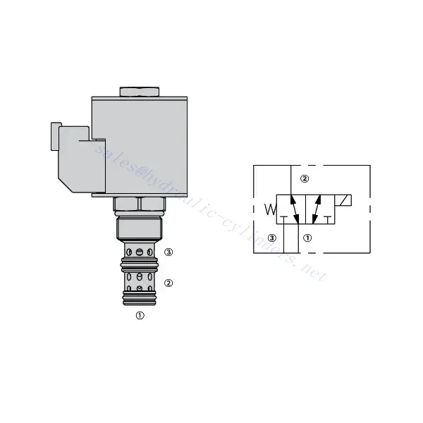
The 30SD10-34 solenoid directional valve is a cutting-edge industrial component designed to provide precise and reliable fluid control in a wide range of applications. With its advanced features, durable construction, and user-friendly design, this solenoid directional valve offers enhanced performance and efficiency.
The 30SD10-34 solenoid directional valve is a reliable and versatile component that offers precise fluid control in industrial applications. Its robust construction, precision control, and reliable performance make it an ideal choice for enhancing the efficiency and productivity of your fluid control systems. By following the recommended usage methods and maintenance guidelines, you can ensure optimal performance and longevity of the 30SD10-34 solenoid directional valve in your industrial operations.
30SD10-34 Solenoid Directional Valve Characteristics:
- Robust Construction: The 30SD10-34 solenoid directional valve is built with high-quality materials and meticulous craftsmanship, ensuring durability and longevity. Its robust construction allows it to withstand demanding industrial environments, providing reliable performance even under harsh conditions.
- Versatile Functionality: This solenoid directional valve offers versatile functionality, making it suitable for various applications. It effectively controls the direction of fluid flow, allowing precise and efficient operation in different industrial systems.
- Precision Control: With exceptional precision, the 30SD10-34 solenoid directional valve enables accurate control over fluid flow. It allows for precise regulation and adjustment of fluid direction and pressure, ensuring optimal performance and efficiency in industrial processes.
- Reliable Performance: This solenoid directional valve delivers reliable performance, minimizing the risk of system failures or interruptions. It operates dependably, contributing to increased productivity and reduced downtime in industrial operations.
30SD10-34 Solenoid Directional Valve Parameter:
| Ονομαστική πίεση | 207 bar (3000 psi) | |
| Proof pressure | 350 bar (5075 psi) | |
| Μέγιστη ροή | 22,7 λίτρα/λεπτό (6 gpm) | |
| Υγρό | Ορυκτά ή συνθετικά με λιπαντικές ιδιότητες | |
| Temperature range ℃ | -54 έως 107 ℃ (Σφραγίδες πολυουρεθάνης) | |
| -40 έως 100 ℃ (σφραγίδες Buna N) | ||
| -26 έως 204 ℃ (Φλακάσια φθοράνθρακα) | ||
| Εύρος ιξώδους | 7,4 έως 420 χιλιοστά2/μικρό | |
| Βαθμός μόλυνσης | Το ελάχιστο επίπεδο ρύπανσης είναι το επίπεδο ISO4406 20/18/14 και συνιστάται το επίπεδο 17/15/13 για την παράταση της διάρκειας ζωής. | |
| Εσωτερική διαρροή | ≤ 115 mL/min@207bar | |
| Κοιλότητα | VC10-3 | |
| Βαθμολογία λειτουργίας πηνίου | Συνεχής από 85% έως 115% ονομαστικής τάσης | |
| Response time | First indication of change of state with 100% voltage supplied at80% of nominal flow rating:Energized: 60 msec. ; De-energized: 10 msec. | |
| Αρχική κατανάλωση ρεύματος πηνίου στους 20℃ | Ηλεκτρονικό πηνίο | 1,7A στα 12VDC; 0,85A στα 24VDC |
| D-πηνίο | 1,67A στα 12VDC; 0,83A στα 24VDC | |
| Ελάχιστη τάση εισόδου | 85% ονομαστικής πίεσης στα 207 bar | |
30SD10-34 Solenoid Directional Valve Advantages:
• Πηνίο συνεχούς λειτουργίας
• Αποδοτική κατασκευή υγρού οπλισμού
• Τα φυσίγγια είναι εναλλάξιμα με τάση
• Προαιρετικά αδιάβροχα E-Coils με βαθμολογία έως IP69K
• All ports may be fully pressurized
• Κοινή κοιλότητα βιομηχανίας
• Σκληρυμένα εξαρτήματα για μεγάλη διάρκεια ζωής και χαμηλή διαρροή
Usage Method Of 30SD10-34 Solenoid Directional Valve:
- Integration into System: Integrate the 30SD10-34 solenoid directional valve into the fluid control system following the manufacturer’s guidelines and specifications. Ensure proper alignment and connection between the valve and other system components to achieve optimal performance.
- Electrical Connection: Establish a secure electrical connection for the solenoid directional valve. Refer to the provided wiring diagram and ensure correct polarity to prevent any electrical malfunctions. Follow safety guidelines when working with electrical connections.
- Fluid Flow Direction Control: Utilize the solenoid directional valve to control the direction of fluid flow. The valve is typically equipped with a lever or actuator for manual adjustment. Alternatively, it can be integrated into an automated control system for remote operation.
- Pressure Adjustment: Employ the solenoid directional valve to regulate fluid pressure within the system. By adjusting the valve’s settings, you can achieve the desired pressure levels for optimal performance and efficiency.
How To Plumb Auto Cycle Hydraulic Valve?
Plumbing an auto-cycle hydraulic valve requires careful attention to ensure proper installation and functionality. Follow these steps to plumb an auto-cycle hydraulic valve effectively:
- Συγκεντρώστε τα απαραίτητα εργαλεία και υλικά: Before you begin, make sure you have all the required tools and materials, including hydraulic hoses, fittings, adapters, Teflon tape, wrenches, and a hydraulic fluid reservoir.
- Identify The Valve Ports: Examine the auto-cycle hydraulic valve to identify the different ports. Typically, there will be inlet ports, outlet ports, and possibly additional ports for pressure relief or auxiliary functions.
- Determine The Hydraulic Fluid Flow Direction: Determine the desired flow direction of the hydraulic fluid through the valve. This information is crucial for correctly connecting the inlet and outlet ports.
- Install Fittings And Adapters: Install the appropriate fittings and adapters onto the valve ports. Ensure they are tightened securely, but be careful not to overtighten and damage the threads.
- Apply Teflon Tape: Wrap Teflon tape around the threads of the fittings and adapters. This helps create a tight seal and prevents leaks.
- Connect Hydraulic Hoses: Attach hydraulic hoses to the fittings and adapters on the valve ports. Ensure the hoses are suitable for the hydraulic system’s pressure rating and are of the correct length.
- Secure Hose Connections: Use hose clamps or other suitable methods to secure the hydraulic hoses to the fittings. This prevents the hoses from coming loose during operation.
- Route The Hydraulic hoses: Carefully route the hydraulic hoses to connect the auto-cycle hydraulic valve to the hydraulic fluid reservoir and other hydraulic components, such as cylinders or motors. Avoid sharp bends or kinks in the hoses that could restrict fluid flow.
- Check For Leaks: Once all connections are made, check for leaks. Start by slowly pressurizing the system and inspecting each connection point. If you notice any leaks, tighten the fittings or replace faulty components as necessary.
- Fill The Hydraulic Fluid Reservoir: Fill the hydraulic fluid reservoir with the recommended type and quantity of hydraulic fluid. Refer to the manufacturer’s guidelines for the appropriate fluid specifications.
- Bleed Air From The System: B bleed any air trapped in the hydraulic system to ensure proper operation. Follow the manufacturer’s instructions for bleeding procedures, which typically involve cycling the design and opening bleed valves.
- Test The System: With the plumbing complete, test the auto-cycle hydraulic valve and the overall system’s performance. Verify that the valve functions as intended and that fluid flow is smooth and consistent.
Ικανότητα & χωρητικότητα του εργοστασίου:
(1) Συναρμολόγηση
Διαθέτουμε μια πρώτης τάξεως ανεξάρτητη πλατφόρμα συναρμολόγησης έρευνας και ανάπτυξης. Το εργαστήριο παραγωγής υδραυλικών κυλίνδρων διαθέτει τέσσερις ημιαυτόματες γραμμές συναρμολόγησης ανυψωτικών κυλίνδρων και μία αυτόματη γραμμή συναρμολόγησης κυλίνδρων κλίσης, με σχεδιασμένη ετήσια παραγωγική ικανότητα 1 εκατομμυρίου τεμαχίων. Το εργαστήριο ειδικών κυλίνδρων είναι εξοπλισμένο με διάφορες προδιαγραφές ενός ημιαυτόματου συστήματος συναρμολόγησης καθαρισμού με σχεδιασμένη ετήσια παραγωγική ικανότητα 200.000 και εξοπλισμένο με διάσημο εξοπλισμό κατεργασίας CNC, ένα κέντρο κατεργασίας, έναν ειδικό εξοπλισμό επεξεργασίας κυλίνδρων υψηλής ακρίβειας, μια μηχανή συγκόλλησης ρομπότ, μια αυτόματη μηχανή καθαρισμού, μια αυτόματη μηχανή συναρμολόγησης κυλίνδρων και μια αυτόματη γραμμή παραγωγής βαφής. Υφιστάμενος κρίσιμος εξοπλισμός άνω των 300 σετ (σετ). Η βέλτιστη κατανομή και η αποτελεσματική χρήση των πόρων του εξοπλισμού διασφαλίζουν τις απαιτήσεις ακρίβειας των προϊόντων και καλύπτουν τις ανάγκες υψηλής ποιότητας των προϊόντων.


(2) Κατεργασία
Το εργαστήριο κατεργασίας είναι εξοπλισμένο με ένα προσαρμοσμένο κέντρο τόρνευσης με κεκλιμένη ράγα, κέντρο κατεργασίας, μηχανή λείανσης υψηλής ταχύτητας, ρομπότ συγκόλλησης και άλλο συναφή εξοπλισμό, το οποίο μπορεί να χειριστεί την επεξεργασία κυλινδρικών σωλήνων με μέγιστη εσωτερική διάμετρο 400 mm και μέγιστο μήκος 6 μέτρων.

(3) Συγκόλληση

(4) Βαφή και επίστρωση
Με μικρές και μεσαίες αυτόματες γραμμές επίστρωσης χρωμάτων με βάση το νερό, για την επίτευξη αυτόματης φόρτωσης και εκφόρτωσης ρομπότ και αυτόματου ψεκασμού, η ικανότητα σχεδιασμού 4000 τεμαχίων ανά βάρδια,
Διαθέτουμε επίσης μια ημιαυτόματη γραμμή παραγωγής χρωμάτων για μεγάλους κυλίνδρους που τροφοδοτείται από μια αλυσίδα ισχύος, με δυνατότητα σχεδιασμού 60 κιβωτίων ανά βάρδια.


(5) Δοκιμές
Διαθέτουμε πρώτης τάξεως εγκαταστάσεις επιθεώρησης και δοκιμαστικές κλίνες για να διασφαλίσουμε ότι η απόδοση του κυλίνδρου ανταποκρίνεται στις απαιτήσεις.

Είμαστε ένας από τους καλύτερους κατασκευαστές υδραυλικών κυλίνδρων. Μπορούμε να προσφέρουμε ολοκληρωμένους υδραυλικούς κυλίνδρους. Παρέχουμε επίσης αντίστοιχους γεωργικά κιβώτια ταχυτήτων. Έχουμε εξάγει τα προϊόντα μας σε πελάτες σε όλο τον κόσμο και έχουμε κερδίσει μια καλή φήμη λόγω της ανώτερης ποιότητας των προϊόντων μας και της εξυπηρέτησης μετά την πώληση. Καλωσορίζουμε τους πελάτες στο εσωτερικό και στο εξωτερικό να επικοινωνήσουν μαζί μας για να διαπραγματευτούν τις επιχειρήσεις, να ανταλλάξουν πληροφορίες και να συνεργαστείτε μαζί μας!


