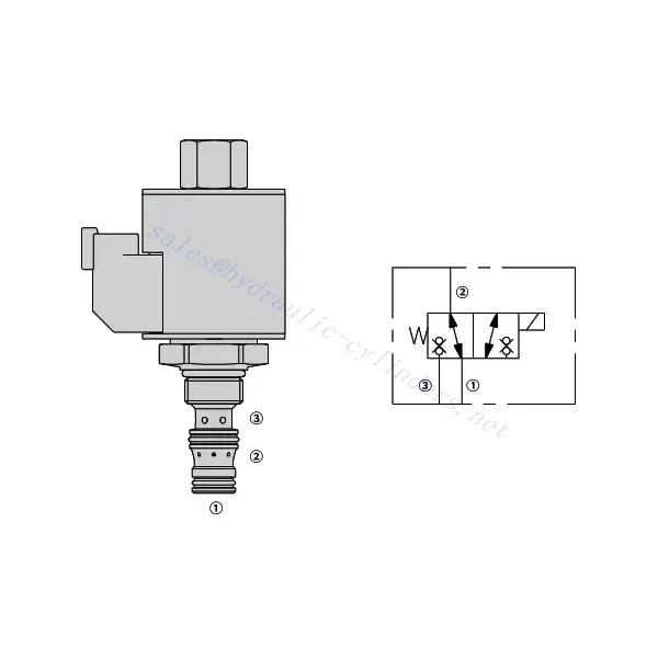
30SD38-38 Solenoid Directional Valve
Ως ένας από τους κατασκευαστές, προμηθευτές και εξαγωγείς υδραυλικών κυλίνδρων μηχανικών προϊόντων, προσφέρουμε υδραυλικούς κυλίνδρους και πολλά άλλα προϊόντα.
Παρακαλούμε επικοινωνήστε μαζί μας για λεπτομέρειες.
Ταχυδρομείο:sales@hydraulic-cylinders.net
Κατασκευαστής προμηθευτής εξαγωγέας υδραυλικών κυλίνδρων.
30SD38-38 Solenoid Directional Valve
The 30SD38-38 solenoid directional valve is a highly efficient and versatile component that plays a pivotal role in fluid control systems. This valve is designed to deliver precise and reliable fluid control and offers exceptional performance and durability.
The 30SD38-38 solenoid directional valve is a reliable and efficient fluid control solution for various industrial applications. With its robust construction, efficient performance, and versatile mounting options, this valve provides precise control over fluid flow and enhances overall system performance. By following proper usage methods and implementing regular maintenance practices, you can ensure optimal functionality and longevity of the 30SD38-38 solenoid directional valve, making it an excellent choice for your fluid control needs.
30SD38-38 Solenoid Directional Valve Characteristics:
- Robust Construction: The 30SD38-38 solenoid directional valve is constructed with high-quality materials, ensuring durability and resistance to wear and corrosion. Its rugged design allows it to withstand harsh operating conditions, making it suitable for various industrial applications.
- Efficient Performance: Powered by a solenoid, this valve provides rapid response times, enabling quick adjustments to fluid flow and pressure. The efficient operation ensures precise control and seamless integration into automated processes.
- Versatile Mounting Options: The valve offers flexible mounting options, including inline, manifold, or subplate configuration. This versatility allows for easy installation and integration into various fluid control systems, accommodating different application requirements.
30SD38-38 Solenoid Directional Valve Parameter:
| Ονομαστική πίεση | 207 bar (3000 psi) | |
| Μέγιστη ροή | Δείτε το διάγραμμα απόδοσης | |
| Εσωτερική διαρροή | ≤5 drops/min@207bar | |
| Βαθμολογία λειτουργίας πηνίου | Συνεχής από 85% έως 115% ονομαστικής τάσης | |
| Αρχική κατανάλωση ρεύματος πηνίου στους 20℃ | Ηλεκτρονικό πηνίο | 1,7A στα 12VDC; 0,85A στα 24VDC |
| D-πηνίο | 1,67A στα 12VDC; 0,83A στα 24VDC | |
| Ελάχιστη τάση εισόδου | 85% ονομαστικής πίεσης στα 207 bar (3000 psi) | |
| Κοιλότητα | VC08-3 | |
| Υγρό | Ορυκτά ή συνθετικά με λιπαντικές ιδιότητες | |
| Εύρος θερμοκρασίας υγρού ℃ | -54 έως 107 ℃ (Σφραγίδες πολυουρεθάνης) | |
| -40 έως 100 ℃ (σφραγίδες Buna N) | ||
| -26 έως 204 ℃ (Φλακάσια φθοράνθρακα) | ||
| Εύρος ιξώδους | 7,4 έως 420 χιλιοστά2/μικρό | |
| Βαθμός μόλυνσης | Το ελάχιστο επίπεδο ρύπανσης είναι το επίπεδο ISO4406 20/18/14 και συνιστάται το επίπεδο 17/15/13 για την παράταση της διάρκειας ζωής. | |
30SD38-38 Solenoid Directional Valve Advantages:
• Πηνίο συνεχούς λειτουργίας
• Τα φυσίγγια είναι εναλλάξιμα με τάση
• Προαιρετικά αδιάβροχα E-Coils με βαθμολογία έως IP69K
• Αποδοτική κατασκευή υγρού οπλισμού
• Κοινή κοιλότητα βιομηχανίας
• Σκληρυμένα μέρη για μεγάλη διάρκεια ζωής
Usage Method Of 30SD38-38 Solenoid Directional Valve:
- Determine the application requirements: Identify the specific fluid control needs of your system. Consider factors such as flow rate, pressure, and direction to select the appropriate valve configuration.
- Mount the valve: Choose the suitable mounting option based on your system’s layout and available space. Ensure that the valve is securely positioned and aligned with the fluid lines.
- Connect the fluid lines: Use compatible fittings and connectors to establish the necessary connections between the valve and the fluid lines. Ensure tight and leak-free connections.
- Electrical connection: Connect the solenoid valve to the appropriate power source following the manufacturer’s instructions. Ensure proper wiring and observe safety precautions.
- Test and adjust: Once the valve is installed and connected, gradually introduce fluid flow and monitor its behavior. Test different operating conditions and adjust the valve settings as needed to achieve the desired fluid control.
How To Replace A Shower Mixing Valve Cartridge?
Replacing a shower mixing valve cartridge is a common DIY task that can help restore proper water temperature and flow control. Here’s a step-by-step guide on how to replace a shower mixing valve cartridge:
- Gather the necessary tools: Before starting the replacement process, gather the following tools: adjustable wrench, Phillips screwdriver, flathead screwdriver, pliers, Allen wrench (if applicable), and a replacement cartridge specific to your shower valve model.
- Turn off the water supply: Locate the main water shut-off valve for your home and turn it off to stop the water flow to the shower. If there isn’t a dedicated shut-off valve for the shower, you may need to shut off the main water supply.
- Remove the handle and trim: Start by removing the handle. Depending on the type of handle, you may need to locate a set screw or a decorative cap covering the screw. Use a flathead or Phillips screwdriver to remove the screw or pry off the cap, allowing you to detach the handle. Next, remove any trim or decorative coverings around the valve by gently pulling or unscrewing them.
- Access the cartridge: Depending on the valve design, you may need to remove additional components to access the cartridge. This can include a retaining nut, sleeve, or escutcheon plate. Use the appropriate tools to remove these components and expose the cartridge.
- Remove the old cartridge: Once you have clear access to the cartridge, use pliers or a specialized cartridge removal tool, if provided, to carefully pull out the old cartridge. Wiggle it back and forth if necessary. Be cautious not to damage any surrounding plumbing connections.
- Clean the valve body: Before installing the new cartridge, clean the valve body thoroughly to remove any debris or mineral buildup. Wipe it with a clean cloth or use a mild cleaning solution if needed.
- Install the new cartridge: Take the replacement cartridge and align it with the valve body, ensuring that any tabs or notches match up correctly. Push the cartridge firmly into place until it sits flush with the valve body.
- Reassemble the valve: Put back any components you removed earlier, such as the retaining nut, sleeve, or escutcheon plate. Make sure they are tightened securely but avoid overtightening.
- Test for leaks: Turn on the water supply and carefully observe the valve for any leaks. If you notice any leaks, tighten the connections or adjust the cartridge as needed. Check both the hot and cold water settings to ensure proper temperature control.
- Reinstall the trim and handle: Once you’ve confirmed that there are no leaks, reinstall the trim or decorative coverings over the valve. Slide the handle back onto the cartridge stem and secure it with the set screw or by replacing the decorative cap.
- Restore water supply: Finally, turn on the main water supply or the dedicated shut-off valve for the shower and test the functionality of the new cartridge. Verify that the water temperature and flow can be adjusted smoothly.
Ικανότητα & χωρητικότητα του εργοστασίου:
(1) Συναρμολόγηση
Διαθέτουμε μια πρώτης τάξεως ανεξάρτητη πλατφόρμα συναρμολόγησης έρευνας και ανάπτυξης. Το εργαστήριο παραγωγής υδραυλικών κυλίνδρων διαθέτει τέσσερις ημιαυτόματες γραμμές συναρμολόγησης ανυψωτικών κυλίνδρων και μία αυτόματη γραμμή συναρμολόγησης κυλίνδρων κλίσης, με σχεδιασμένη ετήσια παραγωγική ικανότητα 1 εκατομμυρίου τεμαχίων. Το εργαστήριο ειδικών κυλίνδρων είναι εξοπλισμένο με διάφορες προδιαγραφές ενός ημιαυτόματου συστήματος συναρμολόγησης καθαρισμού με σχεδιασμένη ετήσια παραγωγική ικανότητα 200.000 και εξοπλισμένο με διάσημο εξοπλισμό κατεργασίας CNC, ένα κέντρο κατεργασίας, έναν ειδικό εξοπλισμό επεξεργασίας κυλίνδρων υψηλής ακρίβειας, μια μηχανή συγκόλλησης ρομπότ, μια αυτόματη μηχανή καθαρισμού, μια αυτόματη μηχανή συναρμολόγησης κυλίνδρων και μια αυτόματη γραμμή παραγωγής βαφής. Υφιστάμενος κρίσιμος εξοπλισμός άνω των 300 σετ (σετ). Η βέλτιστη κατανομή και η αποτελεσματική χρήση των πόρων του εξοπλισμού διασφαλίζουν τις απαιτήσεις ακρίβειας των προϊόντων και καλύπτουν τις ανάγκες υψηλής ποιότητας των προϊόντων.


(2) Κατεργασία
Το εργαστήριο κατεργασίας είναι εξοπλισμένο με ένα προσαρμοσμένο κέντρο τόρνευσης με κεκλιμένη ράγα, κέντρο κατεργασίας, μηχανή λείανσης υψηλής ταχύτητας, ρομπότ συγκόλλησης και άλλο συναφή εξοπλισμό, το οποίο μπορεί να χειριστεί την επεξεργασία κυλινδρικών σωλήνων με μέγιστη εσωτερική διάμετρο 400 mm και μέγιστο μήκος 6 μέτρων.

(3) Συγκόλληση

(4) Βαφή και επίστρωση
Με μικρές και μεσαίες αυτόματες γραμμές επίστρωσης χρωμάτων με βάση το νερό, για την επίτευξη αυτόματης φόρτωσης και εκφόρτωσης ρομπότ και αυτόματου ψεκασμού, η ικανότητα σχεδιασμού 4000 τεμαχίων ανά βάρδια,
Διαθέτουμε επίσης μια ημιαυτόματη γραμμή παραγωγής χρωμάτων για μεγάλους κυλίνδρους που τροφοδοτείται από μια αλυσίδα ισχύος, με δυνατότητα σχεδιασμού 60 κιβωτίων ανά βάρδια.


(5) Δοκιμές
Διαθέτουμε πρώτης τάξεως εγκαταστάσεις επιθεώρησης και δοκιμαστικές κλίνες για να διασφαλίσουμε ότι η απόδοση του κυλίνδρου ανταποκρίνεται στις απαιτήσεις.

Είμαστε ένας από τους καλύτερους κατασκευαστές υδραυλικών κυλίνδρων. Μπορούμε να προσφέρουμε ολοκληρωμένους υδραυλικούς κυλίνδρους. Παρέχουμε επίσης αντίστοιχους γεωργικά κιβώτια ταχυτήτων. Έχουμε εξάγει τα προϊόντα μας σε πελάτες σε όλο τον κόσμο και έχουμε κερδίσει μια καλή φήμη λόγω της ανώτερης ποιότητας των προϊόντων μας και της εξυπηρέτησης μετά την πώληση. Καλωσορίζουμε τους πελάτες στο εσωτερικό και στο εξωτερικό να επικοινωνήσουν μαζί μας για να διαπραγματευτούν τις επιχειρήσεις, να ανταλλάξουν πληροφορίες και να συνεργαστείτε μαζί μας!
Υδραυλικός κύλινδρος Εφαρμογή:
