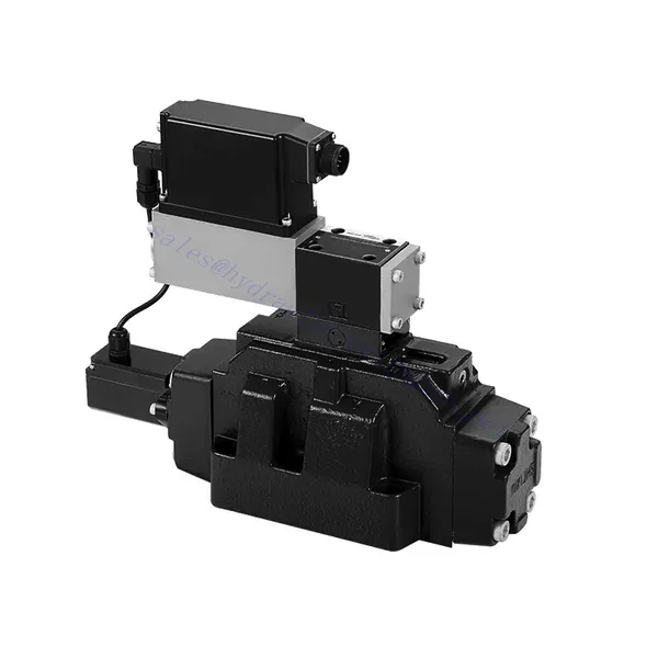
4WRLE Series Pilot Operated Proportional Directional Hydraulic Valve
Ως ένας από τους κατασκευαστές, προμηθευτές και εξαγωγείς υδραυλικών κυλίνδρων μηχανικών προϊόντων, προσφέρουμε υδραυλικούς κυλίνδρους και πολλά άλλα προϊόντα.
Παρακαλούμε επικοινωνήστε μαζί μας για λεπτομέρειες.
Ταχυδρομείο:sales@hydraulic-cylinders.net
Κατασκευαστής προμηθευτής εξαγωγέας υδραυλικών κυλίνδρων.
4WRLE Series Pilot Operated Proportional Directional Hydraulic Valve
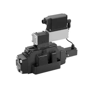
The 4WRLE series pilot-operated proportional directional hydraulic valve is a cutting-edge hydraulic component that revolutionizes fluid control in hydraulic systems. This valve combines pilot-operated technology with proportional directional control, offering precise flow regulation and exceptional efficiency.
The 4WRLE series pilot-operated proportional directional hydraulic valve elevates hydraulic control to new heights of precision and efficiency. With its pilot-operated technology and proportional directional control, this valve ensures accurate flow regulation, optimized energy consumption, and enhanced system performance. By following the recommended usage methods and maintenance guidelines, you can unleash the full potential of the 4WRLE series valve and achieve superior hydraulic control. Upgrade your hydraulic system today and experience the power of precision with the 4WRLE series pilot-operated proportional directional hydraulic valve.
4WRLE Series Pilot Operated Proportional Directional Hydraulic Valve Key Characteristics:
- Pilot Operated Technology:
- The 4WRLE series valve incorporates pilot-operated technology, allowing precise fluid flow control and pressure regulation.
- This technology enables efficient energy usage and reduces heat generation, resulting in improved overall system performance and reduced operating costs.
- Αναλογικός κατευθυντικός έλεγχος:
- With its proportional directional control capability, this valve provides accurate and balanced flow adjustment based on control signals.
- The proportional control allows for smooth and precise control of hydraulic actuators, enhancing system performance and minimizing wear and tear.
- Ευέλικτη λειτουργικότητα:
- The 4WRLE series valve offers versatile control over fluid direction, making it suitable for a wide range of hydraulic applications.
- Whether it’s controlling cylinders, motors, or other hydraulic components, this valve ensures seamless activation and deactivation in different directions, enhancing system flexibility and adaptability.
- Υψηλή χωρητικότητα ροής:
- Designed to handle high flow rates, the 4WRLE series valve delivers exceptional performance even in demanding applications.
- Its robust construction and optimized flow channels ensure reliable operation and consistent flow control, meeting the requirements of high-power hydraulic systems.
4WRLE Series Pilot Operated Proportional Directional Hydraulic Valve Parameter:
NG6
| Γενικός | |||||||
| Σχέδιο | Βαλβίδα πηνίου, άμεσης λειτουργίας, με χαλύβδινο χιτώνιο | ||||||
| Κίνηση | Αναλογικό σωληνοειδές με έλεγχο θέσης, OBE | ||||||
| Τύπος σύνδεσης | Τοποθέτηση υποπλάκας, σχέδιο θύρας σύμφωνα με το πρότυπο ISO 4401-03-02-0-05 | ||||||
| Θέση εγκατάστασης | Κάθε | ||||||
| Εύρος θερμοκρασίας περιβάλλοντος | ℃ | -20…+50 | |||||
| Βάρος | Κιλά | περίπου 2,75 | |||||
| Μέγιστη αντοχή σε κραδασμούς (συνθήκη δοκιμής) | Μέγιστο 25 g, δοκιμή δόνησης χώρου προς όλες τις κατευθύνσεις (24 ώρες) | ||||||
| Υδραυλικός (μετρημένο στα p=100bar, με HLP46 σε ϑέλαιο = 40℃ ±5℃) | |||||||
| Ρευστό υπό πίεση | Ορυκτέλαιο (HL, HLP) σύμφωνα με το DIN 51 524 | ||||||
| Εύρος ιξώδους | συνιστάται | mm²/s | 20…100 | ||||
| μέγιστο επιτρεπόμενο | mm²/s | 10…800 | |||||
| Εύρος θερμοκρασίας ρευστού πίεσης | ℃ | -20 έως +70 | |||||
| Μέγιστος επιτρεπόμενος βαθμός μόλυνσης του ρευστού υπό πίεση Κατηγορία καθαρότητας σύμφωνα με το πρότυπο ISO 4406 (c) | Τάξη 18/16/13 | ||||||
| Ονομαστική ροή (Δp = 35 bar ανά ακμή) | Λ/λεπτό | 2 | 4 | 12 | 24 | 40 | |
| Μέγιστη λειτουργούσα πίεση | μπαρ | Λιμένας Α, Β, Π: 315 | |||||
| Μέγιστη πίεση | μπαρ | Λιμάνι Τ: 250 | |||||
| Ροή διαρροής στα 100 bar | Γραμμικός | cm³/λεπτό | <150 | <180 | <300 | <500 | <900; |
| Μη γραμμικό | cm³/λεπτό | / | / | / | <300 | <450; | |
| Στατικό/Δυναμικό | |||||||
| Υστέρηση | % | ≤0,2 | |||||
| Χρόνος ενεργοποίησης για το βήμα σήματος 0 … 100% | ms | 10 | |||||
| Μετατόπιση θερμοκρασίας | Μηδενική μετατόπιση < 1% σε ΔT=40℃ | ||||||
| Μηδενική αποζημίωση | Από το εργοστάσιο ±1% | ||||||
| Ηλεκτρικά, ηλεκτρονικά ελέγχου ενσωματωμένα στη βαλβίδα | |||||||
| Σχετικός κύκλος λειτουργίας | % | 100ED | |||||
| Βαθμός προστασίας | IP65 | ||||||
| Σύνδεση | Βύσμα σύνδεσης 6P+PE, DIN 43563 | ||||||
| Τάση τροφοδοσίας Τερματικός σταθμός Α Τερματικός σταθμός Β |
24VDCόνομα | ||||||
| ελάχ. 21VDC / μέγ. 40VDC | |||||||
| 0V (μέγιστο 2 κυματισμός) | |||||||
| Προστασία με ασφάλεια, εξωτερική | AF | 2.5 | |||||
| είσοδος, έκδοση «A1» Τερματικός σταθμός D (Uμι) Τερματικός σταθμός Ε |
Διαφορικός ενισχυτής, Ri = 100 kΩ | ||||||
| 0…±10V | |||||||
| 0V | |||||||
| Είσοδος, έκδοση «F1» Τερματικός σταθμός D (ID-E) Τερματικός σταθμός Ε (ID-E) |
Φορτίο, Rσς = 200 Ω | ||||||
| 4…12…20mA | |||||||
| Βρόχος ρεύματος ΙΔΕ απόδοση | |||||||
| Σήμα δοκιμής, έκδοση «A1» Τερματικός σταθμός F (UTest) Τερματικός σταθμός Γ |
LVDT | ||||||
| 0…±10V | |||||||
| Αναφορά 0 V | |||||||
| Σήμα δοκιμής, έκδοση «F1» Τερματικός σταθμός F (I) Ποδοσφαιρική Ομοσπονδία ) Τερματικός σταθμός C (I) Ποδοσφαιρική Ομοσπονδία ) |
Σήμα LVDT 4 … (12) … 20 mA σε εξωτερικό φορτίο 200 … 500 Ωμέγιστο | ||||||
| 4 … (12) … 20mA (έξοδος) | |||||||
| Βρόχος ρεύματος ΙΠοδοσφαιρική Ομοσπονδία απόδοση | |||||||
| Προσαρμογή | Βαθμονομημένο πριν από την παράδοση, βλέπε χαρακτηριστικές καμπύλες | ||||||
NG10
| Γενικός | |||||
| Σχέδιο | Βαλβίδα πηνίου, άμεσης λειτουργίας, με χαλύβδινο χιτώνιο | ||||
| Κίνηση | Αναλογικό σωληνοειδές με έλεγχο θέσης, OBE | ||||
| Τύπος σύνδεσης | Θύρα πλάκας, μοτίβο θυρών (ISO 4401-05-04-0-05) | ||||
| Θέση εγκατάστασης | Κάθε | ||||
| Εύρος θερμοκρασίας περιστάσεων | ℃ | -20…+50 | |||
| Βάρος | Κιλά | περίπου 7,1 | |||
| Μέγιστη αντοχή σε κραδασμούς (συνθήκη δοκιμής) | Μέγιστο 25 g, δοκιμή δόνησης χώρου προς όλες τις κατευθύνσεις (24 ώρες) | ||||
| Υδραυλικό (μετρημένο με HLP 46, ϑέλαιο =40℃ ±5℃) | |||||
| Ρευστό υπό πίεση | Υδραυλικό λάδι σύμφωνα με το πρότυπο DIN 51524…535 | ||||
| Εύρος ιξώδους | συνιστάται | mm²/s | 20…100 | ||
| Μέγιστο επιτρεπόμενο | mm²/s | 10…800 | |||
| Εύρος θερμοκρασίας ρευστού πίεσης | ℃ | -20 έως +70 | |||
| Μέγιστος επιτρεπόμενος βαθμός μόλυνσης του υδραυλικού υγρού, κατηγορία καθαριότητας σύμφωνα με το πρότυπο ISO 4406 (c) | Τάξη 18/16/13 | ||||
| Ονομαστική ροή (Δp = 35 bar ανά ακμή) | Λ/λεπτό | 50 | 100 | ||
| Μέγιστη λειτουργούσα πίεση | μπαρ | Λιμάνι PAB: 315 | |||
| Μέγιστη πίεση | μπαρ | Λιμάνι Τ: 250 | |||
| Ροή διαρροής στα 100 bar | Γραμμικός | cm³/λεπτό | <1200 | <1500 | |
| Μη γραμμικό | cm³/λεπτό | <600 | <600 | ||
| Στατικό/Δυναμικό | |||||
| Υστέρηση | % | ≤0,2 | |||
| Χρόνος ενεργοποίησης για το βήμα σήματος 0 … 100% | ms | 25 | |||
| Μετατόπιση θερμοκρασίας | Μηδενική μετατόπιση < 1% σε ΔT=40℃ | ||||
| Μηδενική αποζημίωση | Από το εργοστάσιο ±1% | ||||
| Ηλεκτρικά, ηλεκτρονικά ελέγχου ενσωματωμένα στη βαλβίδα | |||||
| Σχετικός κύκλος λειτουργίας | % | 100ED | |||
| Βαθμός προστασίας | IP65 (με τοποθετημένο και κλειδωμένο σύνδεσμο ζευγαρώματος) | ||||
| Σύνδεση | Συνδετικός σύνδεσμος 6P+PE, DIN 43563 | ||||
| Τάση τροφοδοσίας Τερματικός σταθμός Α Τερματικός σταθμός Β |
24VDCόνομα | ||||
| ελάχ. 21VDC / μέγ. 40VDC | |||||
| Μέγιστη τάση κύματος 2 VDC | |||||
| Προστασία με ασφάλεια, εξωτερική | AF | 2.5 | |||
| Είσοδος, έκδοση «A1» Τερματικός σταθμός D (Uμι) Τερματικός σταθμός Ε |
Διαφορικός ενισχυτής, Ri = 100 kΩ | ||||
| 0…±10V | |||||
| 0V | |||||
| Είσοδος, έκδοση «F1» Τερματικός σταθμός D (IΔΕ) Τερματικός σταθμός Ε (Ι)ΔΕ) |
Φορτίο, Rσς = 200 | ||||
| 4…12…20mA | |||||
| Βρόχος ρεύματος ΙΔΕ απόδοση | |||||
| Σήμα δοκιμής, έκδοση «A1» Τερματικό F (UΔοκιμή) Τερματικός σταθμός Γ |
LVDT | ||||
| 0…±10V | |||||
| Αναφορά 0 V | |||||
| Σήμα δοκιμής, έκδοση «F1» Τερματικός σταθμός F (I) Ποδοσφαιρική Ομοσπονδία ) Τερματικός σταθμός C (I) Ποδοσφαιρική Ομοσπονδία ) |
LVDT | ||||
| Έξοδος 4…20 mA | |||||
| Βρόχος ρεύματος ΙΠοδοσφαιρική Ομοσπονδία ανατροφοδότηση | |||||
4WRLE Series Pilot Operated Proportional Directional Hydraulic Valve Advantages:
• Σερβοηλεκτροβαλβίδα άμεσης δράσης με έμβολο ελέγχου και χιτώνιο βαλβίδας, με απόδοση σερβο
• Single-side drive, optional, with power-off safety function
Ηλεκτρομαγνητική βαλβίδα ελέγχου με ενσωματωμένη ανάδραση και ενσωματωμένη πλακέτα ενισχυτή (OBE), εργοστασιακά προκαθορισμένη
• Ηλεκτρική σύνδεση Διαφορικός ενισχυτής εισόδου σήματος 6P+PE με διεπαφή, είσοδος προαιρετική A1: ±10V ή διεπαφή F1: 4…20mA (Rsh =200Ω)
• Panel mounting: the mounting surface complies with ISO 4401-03-02
Usage Method Of 4WRLE Series Pilot Operated Proportional Directional Hydraulic Valve:
- System Assessment:
- Evaluate your hydraulic system and define the specific flow and directional control requirements.
- Identify whether the 4WRLE series valve is compatible with your system based on factors such as flow capacity, pressure rating, and compatibility with your application.
- Επιλογή βαλβίδας:
- Select the appropriate variant of the 4WRLE series valve based on your system parameters, flow requirements, and directional control needs.
- Consider factors such as maximum flow rate, pressure rating, response time, and environmental operating conditions.
- Εγκατάσταση:
- Follow the manufacturer’s installation instructions carefully to ensure proper alignment and secure valve mounting.
- Create leak-free connections and ensure correct flow direction alignment to guarantee optimal performance.
- Ενσωμάτωση σήματος ελέγχου:
- Συνδέστε τα καλώδια σήματος ελέγχου της βαλβίδας σε μια κατάλληλη συσκευή ελέγχου, όπως έναν αναλογικό ενισχυτή ή μια ηλεκτρονική μονάδα ελέγχου.
- Ensure proper wiring and compatibility between the valve and control device to achieve accurate and responsive control.
How To Hook Up A Hydraulic Flow Control Valve?
To hook up a hydraulic flow control valve, follow these steps:
- Identify Valve Type: Determine the specific type of flow control valve you are working with. Common types include needle valves, adjustable flow control valves, or pressure-compensated flow control valves. Ensure that the valve is suitable for your application and compatible with your hydraulic system.
- Gather Required Tools and Materials: Collect the necessary tools and materials, including appropriate hydraulic fittings, adapters, hoses, and wrenches.
- Προετοιμασία του υδραυλικού συστήματος: Shut down the hydraulic system and relieve any pressure in the system by activating the relief valve or retracting any hydraulic cylinders. This step is crucial for safety.
- Identify Flow Direction: Identify the flow direction in your hydraulic system. Typically, the flow direction is indicated by arrows on the hydraulic components. Ensure that you understand the correct flow direction before proceeding.
- Locate Installation Point: Determine the optimal location to install the flow control valve in your hydraulic system. Consider factors such as accessibility, proximity to the actuator or hydraulic component, and ease of adjustment.
- Τοποθετήστε τη βαλβίδα: Securely mount the flow control valve in the chosen location using appropriate brackets or clamps. Ensure the valve is positioned correctly, aligning the inlet and outlet ports with the flow direction.
- Συνδέστε τις θύρες εισόδου και εξόδου: Attach hydraulic hoses or tubing to the inlet and outlet ports of the flow control valve. Use suitable hydraulic fittings and adapters to create a leak-free connection. Tighten the connections using wrenches to ensure a secure fit, but avoid over-tightening.
- Adjust the Flow Control: Depending on the type of flow control valve, it may have adjustable features such as a needle valve or a flow control knob. Adjust the valve according to your desired flow rate or speed. Refer to the manufacturer’s instructions for specific adjustment procedures.
- Δοκιμάστε το σύστημα: Once the flow control valve is installed and adjusted, slowly restore hydraulic system pressure. Test the system to ensure that the flow control valve is functioning correctly. Monitor the flow rate or speed of the hydraulic actuator to verify that it is within the desired range.
- Fine-tune and Monitor: Adjust the flow control valve to achieve the desired flow rate or speed. Regularly monitor the hydraulic system for leaks, pressure inconsistencies, or unusual behavior.
Ικανότητα & χωρητικότητα του εργοστασίου:
(1) Συναρμολόγηση
Διαθέτουμε μια πρώτης τάξεως ανεξάρτητη πλατφόρμα συναρμολόγησης έρευνας και ανάπτυξης. Το εργαστήριο παραγωγής υδραυλικών κυλίνδρων διαθέτει τέσσερις ημιαυτόματες γραμμές συναρμολόγησης ανυψωτικών κυλίνδρων και μία αυτόματη γραμμή συναρμολόγησης κυλίνδρων κλίσης, με σχεδιασμένη ετήσια παραγωγική ικανότητα 1 εκατομμυρίου τεμαχίων. Το εργαστήριο ειδικών κυλίνδρων είναι εξοπλισμένο με διάφορες προδιαγραφές ενός ημιαυτόματου συστήματος συναρμολόγησης καθαρισμού με σχεδιασμένη ετήσια παραγωγική ικανότητα 200.000 και εξοπλισμένο με διάσημο εξοπλισμό κατεργασίας CNC, ένα κέντρο κατεργασίας, έναν ειδικό εξοπλισμό επεξεργασίας κυλίνδρων υψηλής ακρίβειας, μια μηχανή συγκόλλησης ρομπότ, μια αυτόματη μηχανή καθαρισμού, μια αυτόματη μηχανή συναρμολόγησης κυλίνδρων και μια αυτόματη γραμμή παραγωγής βαφής. Υφιστάμενος κρίσιμος εξοπλισμός άνω των 300 σετ (σετ). Η βέλτιστη κατανομή και η αποτελεσματική χρήση των πόρων του εξοπλισμού διασφαλίζουν τις απαιτήσεις ακρίβειας των προϊόντων και καλύπτουν τις ανάγκες υψηλής ποιότητας των προϊόντων.


(2) Κατεργασία
Το εργαστήριο κατεργασίας είναι εξοπλισμένο με ένα προσαρμοσμένο κέντρο τόρνευσης με κεκλιμένη ράγα, κέντρο κατεργασίας, μηχανή λείανσης υψηλής ταχύτητας, ρομπότ συγκόλλησης και άλλο συναφή εξοπλισμό, το οποίο μπορεί να χειριστεί την επεξεργασία κυλινδρικών σωλήνων με μέγιστη εσωτερική διάμετρο 400 mm και μέγιστο μήκος 6 μέτρων.

(3) Συγκόλληση

(4) Βαφή και επίστρωση
Με μικρές και μεσαίες αυτόματες γραμμές επίστρωσης χρωμάτων με βάση το νερό, για την επίτευξη αυτόματης φόρτωσης και εκφόρτωσης ρομπότ και αυτόματου ψεκασμού, η ικανότητα σχεδιασμού 4000 τεμαχίων ανά βάρδια,
Διαθέτουμε επίσης μια ημιαυτόματη γραμμή παραγωγής χρωμάτων για μεγάλους κυλίνδρους που τροφοδοτείται από μια αλυσίδα ισχύος, με δυνατότητα σχεδιασμού 60 κιβωτίων ανά βάρδια.


(5) Δοκιμές
Διαθέτουμε πρώτης τάξεως εγκαταστάσεις επιθεώρησης και δοκιμαστικές κλίνες για να διασφαλίσουμε ότι η απόδοση του κυλίνδρου ανταποκρίνεται στις απαιτήσεις.

Είμαστε ένας από τους καλύτερους κατασκευαστές υδραυλικών κυλίνδρων. Μπορούμε να προσφέρουμε ολοκληρωμένους υδραυλικούς κυλίνδρους. Παρέχουμε επίσης αντίστοιχους γεωργικά κιβώτια ταχυτήτων. Έχουμε εξάγει τα προϊόντα μας σε πελάτες σε όλο τον κόσμο και έχουμε κερδίσει μια καλή φήμη λόγω της ανώτερης ποιότητας των προϊόντων μας και της εξυπηρέτησης μετά την πώληση. Καλωσορίζουμε τους πελάτες στο εσωτερικό και στο εξωτερικό να επικοινωνήσουν μαζί μας για να διαπραγματευτούν τις επιχειρήσεις, να ανταλλάξουν πληροφορίες και να συνεργαστείτε μαζί μας!
Υδραυλικός κύλινδρος Εφαρμογή:
