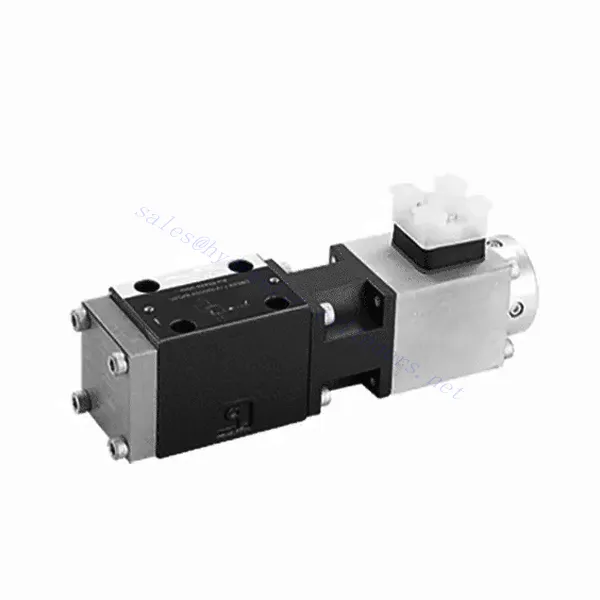
Υδραυλική βαλβίδα ανακούφισης πίεσης σειράς DBE6X(E) αναλογική
Ως ένας από τους κατασκευαστές, προμηθευτές και εξαγωγείς υδραυλικών κυλίνδρων μηχανικών προϊόντων, προσφέρουμε υδραυλικούς κυλίνδρους και πολλά άλλα προϊόντα.
Παρακαλούμε επικοινωνήστε μαζί μας για λεπτομέρειες.
Ταχυδρομείο:sales@hydraulic-cylinders.net
Κατασκευαστής προμηθευτής εξαγωγέας υδραυλικών κυλίνδρων.
Υδραυλική βαλβίδα ανακούφισης πίεσης σειράς DBE6X(E) αναλογική
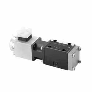
The DBE6X(E) series proportional pressure relief hydraulic Valve is a cutting-edge component that provides accurate and dynamic pressure control in hydraulic systems. With its advanced proportional control technology, this valve ensures optimal performance, efficiency, and safety.
The DBETX series proportional pressure relief hydraulic valve empowers hydraulic systems with precise pressure control, enhanced efficiency, and equipment protection. With its commensurate pressure relief capabilities, this valve ensures optimal performance across various applications. By following the recommended usage methods and maintenance guidelines, you can maximize the benefits and reliability of the DBETX series valve, elevating the performance and control of your hydraulic system. Upgrade your hydraulic setup today and experience superior pressure regulation with the DBETX series proportional pressure relief hydraulic valve.
DBE6X(E) Series Proportional Pressure Relief Hydraulic Valve Key Characteristics:
- Proportional Pressure Relief:
- The DBE6X(E) series valve offers precise and proportional pressure relief, allowing dynamic hydraulic pressure control.
- It ensures accurate pressure regulation in response to varying load conditions, preventing system overload and safeguarding hydraulic components.
- Βελτιωμένη Απόδοση Συστήματος:
- This valve enables precise hydraulic pressure control, resulting in enhanced system efficiency and reduced energy consumption.
- By maintaining the desired pressure levels, it minimizes pressure fluctuations, optimizes system performance, and reduces operational costs.
- Safety and Equipment Protection:
- The DBE6X(E) Series Valve acts as a protective mechanism by limiting the pressure within the hydraulic system, safeguarding equipment and operators.
- It prevents excessive pressure build-up, reducing the risk of component damage, system failures, and potential accidents.
- Proportional Control Functionality:
- With its proportional control technology, the DBE6X(E) series valve offers smooth and precise pressure adjustment.
- It allows for real-time pressure control, enabling seamless integration into various hydraulic systems and applications.
DBE6X(E) Series Proportional Pressure Relief Hydraulic Valve Parameter:
| Γενικός | ||||||
| Κατασκευή | Pilot stage | Poppet valve | ||||
| Main stage | Spool valve | |||||
| Κίνηση | Proportional solenoid without position control, external amplifier | |||||
| Τύπος σύνδεσης | Subplate, mounting hole configuration NG6 (SIO 4401-03-02-094) | |||||
| Θέση εγκατάστασης | Προαιρετικός | |||||
| Εύρος θερμοκρασίας περιστάσεων | ℃ | -20 to +50 | ||||
| Βάρος | Κιλά | 2.2 | ||||
| Vibration resistance, test condition | Max. 25 g, shaken in 3 dimensions (24 h) | |||||
| Hydraulic ( measured with HLP 46, oil = 40℃ ±5℃ ): | ||||||
| Ρευστό υπό πίεση | Hydraulic oil to DIN 51524…535,other fluids after prior consultation | |||||
| Εύρος ιξώδους | συνιστάται | mm²/s | 20…100 | |||
| μέγιστο επιτρεπόμενο | mm²/s | 10…800 | ||||
| Εύρος θερμοκρασίας ρευστού πίεσης | ℃ | -20 to +80 | ||||
| Μέγιστος επιτρεπόμενος βαθμός μόλυνσης του ρευστού υπό πίεση Κατηγορία καθαρότητας σύμφωνα με το πρότυπο ISO 4406 (c) | Τάξη 18/16/13 | |||||
| Direction of flow | See symbol | |||||
| Max. setting pressure (at Qmaxx = 1 L/min) | μπαρ | 80 | 180 | 250 | 315 | |
| Min. settable pressure(当 Qmin = 1 L/min) | μπαρ | 7 | 8 | 9 | 10 | |
| Μέγιστη λειτουργούσα πίεση | μπαρ | Port P:315 | ||||
| Port T:250 | ||||||
| Max. mechanical pressure limitation level,e.g. when solenoid current I>Imax | μπαρ | < 90 | < 190 | < 260 | < 235 | |
| Pilot oil flow | Λ/λεπτό | about 0.6 | ||||
| Μέγιστος ρυθμός ροής | Λ/λεπτό | 40 | ||||
| Ηλεκτρικά δεδομένα | ||||||
| Cyclic duration factor | % | 100 ED | ||||
| Βαθμός προστασίας | IP 65 to DIN 40050 and IEC 14434/5 | |||||
| Solenoid connection | Plug-in connector to DIN 43650/ISO 4400,M16X1.5(2P+PE) | |||||
| Valve with solenoid type | 0.8A | 2.5A | ||||
| Max. solenoid current | Ίμαξ | 0.8A | 2.5A | |||
| Coil resistance R20 | Ω | 22 | 3 | |||
| Max. power consumption at 100% load and operating temperature | VA | 25 | 30 | |||
| Στατικό/Δυναμικό | ||||||
| Υστέρηση | % | ≤ 4 | ||||
| Range of inversion | % | ≤3 | ||||
| Manufacturing tolerance for Pmax | % | ≤10 | ||||
| Response time 100% signal change | ms | On 200 / Off | ||||
DBE6X(E) Series Proportional Pressure Relief Hydraulic Valve Advantages:
• Pilot valve to restrict system pressure (control oil internal only)
• Can adjust by controlling the coil current according to the characteristic curve and the selected electronic control unit
• Solenoid type Imax=0.8 A or 2.5 A
• In the event of electronic control unit failure, the overload protection can function to the highest degree (coil current > Imax)
• Used in valve sub-plate mounting, installation hole follows ISO 441-03-02-0-94,
• Cable sockets follows DIN 43650-AM2
• External electronic control unit with ramp and valve adjustment function VT-SSPA1-508/525-L2X/V0/*
Usage Method Of DBE6X(E) Series Proportional Pressure Relief Hydraulic Valve:
- Αξιολόγηση Συστήματος:
- Evaluate your hydraulic system and identify the specific pressure control requirements.
- Determine if the DBE6X(E) series valve is compatible with your system based on its pressure range, flow capacity, and other specifications.
- Επιλογή βαλβίδας:
- Choose the appropriate DBE6X(E) series valve variant based on your system parameters, pressure range, and flow requirements.
- Λάβετε υπόψη τη μέγιστη ονομαστική πίεση, τον χρόνο απόκρισης και τις συνθήκες λειτουργίας.
- Εγκατάσταση:
- Ακολουθήστε προσεκτικά τις οδηγίες εγκατάστασης του κατασκευαστή, διασφαλίζοντας την σωστή ευθυγράμμιση και την ασφαλή τοποθέτηση της βαλβίδας.
- Συνδέστε τη βαλβίδα στο υδραυλικό σύστημα, διασφαλίζοντας συνδέσεις χωρίς διαρροές και σωστή ευθυγράμμιση της κατεύθυνσης ροής.
- Ρύθμιση πίεσης:
- Utilize the proportional control signal or adjustment mechanism provided with the DBE6X(E) series valve to set the desired pressure relief level.
- Ρυθμίστε τη βαλβίδα σταδιακά, παρακολουθώντας τις μετρήσεις του μανόμετρου και την απόκριση του συστήματος για να επιτύχετε ακριβή έλεγχο της πίεσης.
How To Adjust Hydraulic Flow Control Valve?
Adjusting a hydraulic pressure relief valve allows you to set the desired maximum pressure in a hydraulic system. This is important for maintaining system integrity and preventing damage to components. Here’s a step-by-step guide on how to adjust a hydraulic pressure relief valve:
- Identify the Pressure Relief Valve:
- Locate the pressure relief valve in your hydraulic system. It is typically installed in the hydraulic line and often near the pump or control valve.
- Understand the Valve Design:
- Familiarize yourself with the specific design of the pressure relief valve you are working with. Different valves may have varying adjustment mechanisms, such as a knob, screw, or locknut.
- Προσδιορίστε την επιθυμητή πίεση:
- Assess the requirements of your hydraulic system and determine the desired maximum pressure. This will guide you in adjusting the pressure relief valve accurately.
- Προετοιμασία του συστήματος:
- Before making any adjustments, shut off the hydraulic system and relieve the pressure by moving the control levers back and forth or following the manufacturer’s recommended procedure.
- Locate the Adjustment Mechanism:
- Identify the adjustment mechanism on the pressure relief valve. It could be a knob, screw, or locknut positioned on the valve body or adjacent to it.
- Adjust the Valve:
- If the valve has a knob or handle, turn it clockwise to increase the pressure relief setting or counterclockwise to decrease it. If the valve has a screw, turn it clockwise to increase the pressure relief or counterclockwise to decrease it.
- Κάντε σταδιακές προσαρμογές:
- When adjusting the pressure relief valve, make small, incremental changes to avoid sudden or drastic variations in pressure. This allows you to fine-tune the maximum pressure and achieve the desired performance.
- Observe the System:
- With each adjustment, observe the hydraulic system and its components. Pay attention to the pressure gauge readings to see if they align with the desired maximum pressure.
- Δοκιμή και επαλήθευση:
- Operate the hydraulic system and monitor the pressure to ensure that it remains within the desired range. Check for any pressure fluctuations or irregularities that may indicate the need for further adjustment.
- Κλείδωμα της ρύθμισης:
- Once you have achieved the desired pressure relief setting, secure the adjustment mechanism to prevent unintended changes. Some valves may have a locking nut or set screw that can be tightened to hold the adjustment in place.
- Monitor and Revisit:
- Regularly monitor the pressure relief valve and the hydraulic system. If there are changes in the system or if the desired maximum pressure needs to be adjusted, revisit the pressure relief valve and repeat the adjustment process as needed.
Ικανότητα & χωρητικότητα του εργοστασίου:
(1) Συναρμολόγηση
Διαθέτουμε μια πρώτης τάξεως ανεξάρτητη πλατφόρμα συναρμολόγησης έρευνας και ανάπτυξης. Το εργαστήριο παραγωγής υδραυλικών κυλίνδρων διαθέτει τέσσερις ημιαυτόματες γραμμές συναρμολόγησης ανυψωτικών κυλίνδρων και μία αυτόματη γραμμή συναρμολόγησης κυλίνδρων κλίσης, με σχεδιασμένη ετήσια παραγωγική ικανότητα 1 εκατομμυρίου τεμαχίων. Το εργαστήριο ειδικών κυλίνδρων είναι εξοπλισμένο με διάφορες προδιαγραφές ενός ημιαυτόματου συστήματος συναρμολόγησης καθαρισμού με σχεδιασμένη ετήσια παραγωγική ικανότητα 200.000 και εξοπλισμένο με διάσημο εξοπλισμό κατεργασίας CNC, ένα κέντρο κατεργασίας, έναν ειδικό εξοπλισμό επεξεργασίας κυλίνδρων υψηλής ακρίβειας, μια μηχανή συγκόλλησης ρομπότ, μια αυτόματη μηχανή καθαρισμού, μια αυτόματη μηχανή συναρμολόγησης κυλίνδρων και μια αυτόματη γραμμή παραγωγής βαφής. Υφιστάμενος κρίσιμος εξοπλισμός άνω των 300 σετ (σετ). Η βέλτιστη κατανομή και η αποτελεσματική χρήση των πόρων του εξοπλισμού διασφαλίζουν τις απαιτήσεις ακρίβειας των προϊόντων και καλύπτουν τις ανάγκες υψηλής ποιότητας των προϊόντων.


(2) Κατεργασία
Το εργαστήριο κατεργασίας είναι εξοπλισμένο με ένα προσαρμοσμένο κέντρο τόρνευσης με κεκλιμένη ράγα, κέντρο κατεργασίας, μηχανή λείανσης υψηλής ταχύτητας, ρομπότ συγκόλλησης και άλλο συναφή εξοπλισμό, το οποίο μπορεί να χειριστεί την επεξεργασία κυλινδρικών σωλήνων με μέγιστη εσωτερική διάμετρο 400 mm και μέγιστο μήκος 6 μέτρων.

(3) Συγκόλληση

(4) Βαφή και επίστρωση
Με μικρές και μεσαίες αυτόματες γραμμές επίστρωσης χρωμάτων με βάση το νερό, για την επίτευξη αυτόματης φόρτωσης και εκφόρτωσης ρομπότ και αυτόματου ψεκασμού, η ικανότητα σχεδιασμού 4000 τεμαχίων ανά βάρδια,
Διαθέτουμε επίσης μια ημιαυτόματη γραμμή παραγωγής χρωμάτων για μεγάλους κυλίνδρους που τροφοδοτείται από μια αλυσίδα ισχύος, με δυνατότητα σχεδιασμού 60 κιβωτίων ανά βάρδια.


(5) Δοκιμές
Διαθέτουμε πρώτης τάξεως εγκαταστάσεις επιθεώρησης και δοκιμαστικές κλίνες για να διασφαλίσουμε ότι η απόδοση του κυλίνδρου ανταποκρίνεται στις απαιτήσεις.

Είμαστε ένας από τους καλύτερους κατασκευαστές υδραυλικών κυλίνδρων. Μπορούμε να προσφέρουμε ολοκληρωμένους υδραυλικούς κυλίνδρους. Παρέχουμε επίσης αντίστοιχους γεωργικά κιβώτια ταχυτήτων. Έχουμε εξάγει τα προϊόντα μας σε πελάτες σε όλο τον κόσμο και έχουμε κερδίσει μια καλή φήμη λόγω της ανώτερης ποιότητας των προϊόντων μας και της εξυπηρέτησης μετά την πώληση. Καλωσορίζουμε τους πελάτες στο εσωτερικό και στο εξωτερικό να επικοινωνήσουν μαζί μας για να διαπραγματευτούν τις επιχειρήσεις, να ανταλλάξουν πληροφορίες και να συνεργαστείτε μαζί μας!
Υδραυλικός κύλινδρος Εφαρμογή:
