Υδραυλική βαλβίδα μεταφοράς σειράς KSF
Ως ένας από τους κατασκευαστές, προμηθευτές και εξαγωγείς υδραυλικών κυλίνδρων μηχανικών προϊόντων, προσφέρουμε υδραυλικούς κυλίνδρους και πολλά άλλα προϊόντα.
Παρακαλούμε επικοινωνήστε μαζί μας για λεπτομέρειες.
Ταχυδρομείο:sales@hydraulic-cylinders.net
Κατασκευαστής προμηθευτής εξαγωγέας υδραυλικών κυλίνδρων.
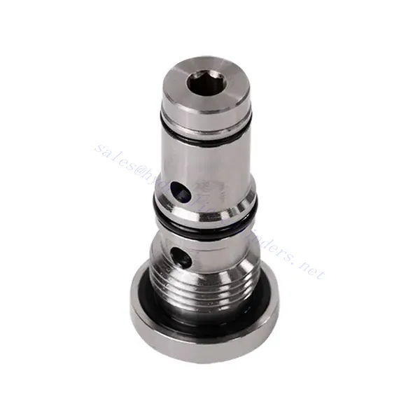
Υδραυλική βαλβίδα μεταφοράς σειράς KSF
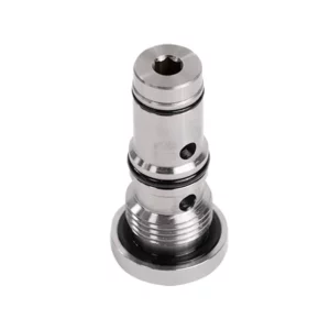
The KSF series shuttle hydraulic valve is a high-performance component designed to enhance fluid flow control in hydraulic systems. With its advanced design and robust construction, this valve offers precise and reliable operation, ensuring optimal system performance.
The KSF series shuttle hydraulic valve is an exceptional solution for fluid flow control in hydraulic systems. With its shuttle valve functionality, robust construction, high flow capacity, and compact design, this valve optimizes performance and ensures efficient utilization of hydraulic power. By following the recommended usage methods and maintenance practices, the KSF series shuttle hydraulic valve delivers reliable operation and extends the lifespan of hydraulic systems. Upgrade your hydraulic system with the KSF series shuttle hydraulic valve and experience enhanced fluid flow control for improved overall system performance.
KSF Series Shuttle Hydraulic Valve Key Characteristics:
- Shuttle Valve Functionality:
- The KSF series valve incorporates a shuttle valve design to divert hydraulic fluid flow between two circuits.
- It enables the selection of the circuit with higher pressure, ensuring efficient utilization of hydraulic power and preventing pressure imbalances.
- Στιβαρή κατασκευή:
- Built with durable materials, the KSF series shuttle hydraulic valve is designed to withstand high-pressure environments and demanding operating conditions.
- Its robust construction ensures longevity and reliability, minimizing downtime and maintenance costs.
- Υψηλή χωρητικότητα ροής:
- The KSF series valve offers a high flow capacity, allowing for efficient transfer of hydraulic fluid between circuits.
- It minimizes pressure drops, ensuring maximum power delivery and system performance.
- Συμπαγής και ευέλικτος σχεδιασμός:
- The valve’s compact design makes it suitable for installations with limited space or weight constraints.
- Its versatility allows easy integration into various hydraulic systems, including industrial machinery, mobile equipment, and power units.
KSF Series Shuttle Hydraulic Valve Parameter:
| Μέγεθος | NG6 | NG10 | |
| Εύρος θερμοκρασίας ρευστού | ℃ | -30 έως +80 (σφραγίδες NBR) | |
| -20 έως +80 (σφραγίδες FKM) | |||
| Εύρος ιξώδους | χιλ.2/μικρό | Recommandation 30~80, άδεια 20~380 | |
| Μέγιστη λειτουργούσα πίεση | μπαρ | 350 | |
| Μέγιστος ρυθμός ροής | Λ/λεπτό | 40 | 60 |
| Βάρος | κιλά | 0.5 | 0.8 |
| Υγρό | Ορυκτέλαιο κατάλληλο για στεγανοποίηση NBR και FKM | ||
| Φωσφορικός εστέρας για σφράγιση FKM | |||
| Βαθμός μόλυνσης | Μέγιστος επιτρεπόμενος βαθμός μόλυνσης υγρού: Κλάση 9. NAS 1638 ή 20/18/15, ISO4406 | ||
KSF Series Shuttle Hydraulic Valve Advantages:
• Seal without leakage
• Cartridge structure for oil block installation
Usage Method Of KSF Series Shuttle Hydraulic Valve:
- Ανάλυση Συστήματος:
- Before installation, perform a comprehensive hydraulic system analysis to determine specific requirements and operating parameters.
- Consider factors such as flow rates, pressure ratings, and compatibility with the KSF series shuttle hydraulic valve.
- Επιλογή βαλβίδας:
- Choose the appropriate KSF series valve variant based on the system’s requirements and specifications.
- Λάβετε υπόψη παράγοντες όπως η ικανότητα ροής, οι ονομαστικές τιμές πίεσης και η συμβατότητα με άλλα εξαρτήματα του συστήματος.
- Εγκατάσταση:
- Follow the manufacturer’s instructions for properly installing the KSF series shuttle hydraulic Valve in the hydraulic system.
- Ensure a secure fit, proper alignment with the fluid flow path, and adequate sealing to prevent leaks.
- Circuit Connection:
- Connect the inlet and outlet ports of the valve to the corresponding circuits that require fluid diversion.
- Ensure proper identification and connection of the high-pressure circuit and low-pressure circuit.
Πώς λειτουργεί μια υδραυλική βαλβίδα ελέγχου ροής;
Μια υδραυλική βαλβίδα ελέγχου ροής είναι μια συσκευή που χρησιμοποιείται για τη ρύθμιση και τον έλεγχο της ταχύτητας του υδραυλικού υγρού μέσα σε ένα υδραυλικό σύστημα. Επιτρέπει στον χειριστή να ρυθμίζει τον ρυθμό ροής του υγρού, αποτρέποντας έτσι την ταχύτητα των υδραυλικών ενεργοποιητών ή ελέγχοντας τον ρυθμό μεταφοράς ενέργειας. Ακολουθεί μια εξήγηση για το πώς λειτουργεί μια υδραυλική βαλβίδα ελέγχου ροής:
- Δομή βαλβίδας:
- Μια υδραυλική βαλβίδα ελέγχου ροής αποτελείται συνήθως από ένα σώμα βαλβίδας με θύρες εισόδου και εξόδου, ένα κινητό καρούλι ή δισκίο και έναν μηχανισμό ενεργοποίησης.
- Το σώμα της βαλβίδας περιέχει εσωτερικές διόδους και θαλάμους που ελέγχουν τη ροή του υδραυλικού υγρού.
- Διαδρομές Ροής Ρευστών:
- Η βαλβίδα ελέγχου ροής έχει μια θύρα εισόδου που συνδέεται με την υδραυλική πηγή ενέργειας, όπως μια αντλία, και μια θύρα εξόδου που συνδέεται με τον υδραυλικό ενεργοποιητή ή άλλο εξάρτημα.
- Η βαλβίδα παρέχει διαφορετικές διαδρομές ροής για το ρευστό, επιτρέποντάς του να ελέγχεται και να ρυθμίζεται.
- Καρούλι ή ρολό:
- Το σώμα της βαλβίδας στεγάζει ένα κινητό καρούλι ή δισκίο που ρυθμίζει τη ροή του υδραυλικού υγρού.
- Το καρούλι μπορεί να ολισθαίνει μέσα στο σώμα της βαλβίδας, ενώ το πτερύγιο μπορεί να κινείται γραμμικά ή να περιστρέφεται για να ανοίγει ή να κλείνει συγκεκριμένες διόδους.
- Μηχανισμός ενεργοποίησης:
- Οι υδραυλικές βαλβίδες ελέγχου ροής μπορούν να ενεργοποιηθούν χειροκίνητα, ηλεκτρικά ή με άλλα μέσα, ανάλογα με τον συγκεκριμένο σχεδιασμό και τις απαιτήσεις εφαρμογής.
- Η χειροκίνητη ενεργοποίηση περιλαμβάνει τη ρύθμιση μιας λαβής, ενός κουμπιού ή ενός μοχλού για να τοποθετήσετε το καρούλι ή το πηνίο.
- Η ηλεκτρική ενεργοποίηση χρησιμοποιεί ηλεκτρομαγνητικά πηνία που λαμβάνουν ηλεκτρικά σήματα για να μετακινήσουν το καρούλι ή το δισκίο, επιτρέποντας τον τηλεχειρισμό και τον αυτοματισμό.
- Θέσεις βαλβίδων:
- Μια υδραυλική βαλβίδα ελέγχου ροής έχει συνήθως πολλαπλές θέσεις που μπορεί να λάβει το καρούλι ή η βαλβίδα ελέγχου ροής, καθεμία από τις οποίες αντιστοιχεί σε έναν συγκεκριμένο ρυθμό ροής.
- Η βαλβίδα μπορεί να έχει μια σειρά από προκαθορισμένες θέσεις ή να προσφέρει συνεχή ρύθμιση για την λεπτή ρύθμιση του ρυθμού ροής.
- Καθώς το καρούλι ή η οπή μετατοπίζεται, ευθυγραμμίζεται με συγκεκριμένα περάσματα, ανοίγοντάς τα ή κλείνοντάς τα για να ελέγχει τη ροή του υγρού.
- Ρύθμιση ροής:
- Ρυθμίζοντας τη θέση του καρουλιού ή του δισκίου, ο χειριστής μπορεί να ελέγξει το μέγεθος των διόδων ροής, ρυθμίζοντας έτσι τον ρυθμό ροής του υδραυλικού υγρού.
- Όταν οι δίοδοι είναι πλήρως ανοιχτές, το υγρό ρέει ελεύθερα, επιτρέποντας τη μέγιστη ροή.
- Το μερικό κλείσιμο των διόδων περιορίζει τη ροή, μειώνοντας τον ρυθμό ροής και ελέγχοντας την ταχύτητα των υδραυλικών ενεργοποιητών.
- Αντιστάθμιση πίεσης:
- Ορισμένες υδραυλικές βαλβίδες ελέγχου ροής ενσωματώνουν μηχανισμούς αντιστάθμισης πίεσης για να διατηρούν σταθερό ρυθμό ροής παρά τις αλλαγές στην πίεση του συστήματος.
- Αυτοί οι μηχανισμοί διασφαλίζουν ότι ο επιθυμητός ρυθμός ροής διατηρείται ακόμη και όταν το σύστημα αντιμετωπίζει διακυμάνσεις στο φορτίο ή την πίεση.
Ικανότητα & χωρητικότητα του εργοστασίου:
(1) Συναρμολόγηση
Διαθέτουμε μια πρώτης τάξεως ανεξάρτητη πλατφόρμα συναρμολόγησης έρευνας και ανάπτυξης. Το εργαστήριο παραγωγής υδραυλικών κυλίνδρων διαθέτει τέσσερις ημιαυτόματες γραμμές συναρμολόγησης ανυψωτικών κυλίνδρων και μία αυτόματη γραμμή συναρμολόγησης κυλίνδρων κλίσης, με σχεδιασμένη ετήσια παραγωγική ικανότητα 1 εκατομμυρίου τεμαχίων. Το εργαστήριο ειδικών κυλίνδρων είναι εξοπλισμένο με διάφορες προδιαγραφές ενός ημιαυτόματου συστήματος συναρμολόγησης καθαρισμού με σχεδιασμένη ετήσια παραγωγική ικανότητα 200.000 και εξοπλισμένο με διάσημο εξοπλισμό κατεργασίας CNC, ένα κέντρο κατεργασίας, έναν ειδικό εξοπλισμό επεξεργασίας κυλίνδρων υψηλής ακρίβειας, μια μηχανή συγκόλλησης ρομπότ, μια αυτόματη μηχανή καθαρισμού, μια αυτόματη μηχανή συναρμολόγησης κυλίνδρων και μια αυτόματη γραμμή παραγωγής βαφής. Υφιστάμενος κρίσιμος εξοπλισμός άνω των 300 σετ (σετ). Η βέλτιστη κατανομή και η αποτελεσματική χρήση των πόρων του εξοπλισμού διασφαλίζουν τις απαιτήσεις ακρίβειας των προϊόντων και καλύπτουν τις ανάγκες υψηλής ποιότητας των προϊόντων.


(2) Κατεργασία
Το εργαστήριο κατεργασίας είναι εξοπλισμένο με ένα προσαρμοσμένο κέντρο τόρνευσης με κεκλιμένη ράγα, κέντρο κατεργασίας, μηχανή λείανσης υψηλής ταχύτητας, ρομπότ συγκόλλησης και άλλο συναφή εξοπλισμό, το οποίο μπορεί να χειριστεί την επεξεργασία κυλινδρικών σωλήνων με μέγιστη εσωτερική διάμετρο 400 mm και μέγιστο μήκος 6 μέτρων.

(3) Συγκόλληση

(4) Βαφή και επίστρωση
Με μικρές και μεσαίες αυτόματες γραμμές επίστρωσης χρωμάτων με βάση το νερό, για την επίτευξη αυτόματης φόρτωσης και εκφόρτωσης ρομπότ και αυτόματου ψεκασμού, η ικανότητα σχεδιασμού 4000 τεμαχίων ανά βάρδια,
Διαθέτουμε επίσης μια ημιαυτόματη γραμμή παραγωγής χρωμάτων για μεγάλους κυλίνδρους που τροφοδοτείται από μια αλυσίδα ισχύος, με δυνατότητα σχεδιασμού 60 κιβωτίων ανά βάρδια.


(5) Δοκιμές
Διαθέτουμε πρώτης τάξεως εγκαταστάσεις επιθεώρησης και δοκιμαστικές κλίνες για να διασφαλίσουμε ότι η απόδοση του κυλίνδρου ανταποκρίνεται στις απαιτήσεις.

Είμαστε ένας από τους καλύτερους κατασκευαστές υδραυλικών κυλίνδρων. Μπορούμε να προσφέρουμε ολοκληρωμένους υδραυλικούς κυλίνδρους. Παρέχουμε επίσης αντίστοιχους γεωργικά κιβώτια ταχυτήτων. Έχουμε εξάγει τα προϊόντα μας σε πελάτες σε όλο τον κόσμο και έχουμε κερδίσει μια καλή φήμη λόγω της ανώτερης ποιότητας των προϊόντων μας και της εξυπηρέτησης μετά την πώληση. Καλωσορίζουμε τους πελάτες στο εσωτερικό και στο εξωτερικό να επικοινωνήσουν μαζί μας για να διαπραγματευτούν τις επιχειρήσεις, να ανταλλάξουν πληροφορίες και να συνεργαστείτε μαζί μας!
Υδραυλικός κύλινδρος Εφαρμογή:
