
Κατευθυντική υδραυλική βαλβίδα σειράς WMM με μηχανική, χειροκίνητη λειτουργία
Κατευθυντική υδραυλική βαλβίδα σειράς WMM με μηχανική, χειροκίνητη λειτουργία
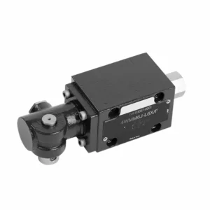
Η κατευθυντική υδραυλική βαλβίδα της σειράς WMM με μηχανική, χειροκίνητη λειτουργία είναι μια ευέλικτη και αξιόπιστη λύση σχεδιασμένη για τον ακριβή έλεγχο υδραυλικών συστημάτων. Αυτή η υδραυλική βαλβίδα προσφέρει βελτιωμένη απόδοση και ευελιξία με τα προηγμένα χαρακτηριστικά της και την στιβαρή κατασκευή της.
Η κατευθυντική υδραυλική βαλβίδα σειράς WMM με μηχανική, χειροκίνητη λειτουργία αποτελεί μια αξιόπιστη και ευέλικτη λύση για υδραυλικά συστήματα. Η αυτόματη χειροκίνητη λειτουργία και ο ακριβής κατευθυντικός έλεγχος προσφέρουν βελτιωμένη ευελιξία και έλεγχο για διάφορες εφαρμογές. Ακολουθώντας τις συνιστώμενες μεθόδους χρήσης και τηρώντας τις τακτικές πρακτικές συντήρησης, η υδραυλική βαλβίδα σειράς WMM θα συνεχίσει να παρέχει αποτελεσματική και αξιόπιστη λειτουργία. Αναβαθμίστε το υδραυλικό σας σύστημα με την κατευθυντική βαλβίδα σειράς WMM και απολαύστε τα οφέλη του βελτιωμένου ελέγχου και της ευελιξίας.
Κατευθυντική υδραυλική βαλβίδα σειράς WMM με μηχανική, χειροκίνητη λειτουργία Βασικά χαρακτηριστικά:
- Μηχανική, Χειροκίνητη λειτουργία:
- Η υδραυλική βαλβίδα σειράς WMM διαθέτει μηχανική, χειροκίνητη λειτουργία, επιτρέποντας στους χειριστές να ελέγχουν τη θέση της βαλβίδας χειροκίνητα.
- Αυτό παρέχει ευελιξία και έλεγχο σε εφαρμογές όπου απαιτείται ή απαιτείται χειροκίνητη λειτουργία.
- Κατευθυντικός έλεγχος:
- Αυτή η υδραυλική βαλβίδα επιτρέπει τον ακριβή κατευθυντικό έλεγχο της ροής του ρευστού εντός του υδραυλικού συστήματος.
- Επιτρέπει στους χειριστές να επιλέξουν την επιθυμητή διαδρομή ροής, εξασφαλίζοντας αποτελεσματική και αξιόπιστη λειτουργία.
- Ανθεκτική κατασκευή:
- Η υδραυλική βαλβίδα σειράς WMM κατασκευάζεται με υλικά υψηλής ποιότητας, εξασφαλίζοντας ανθεκτικότητα και μακροζωία.
- Ο στιβαρός σχεδιασμός του μπορεί να αντέξει απαιτητικές συνθήκες λειτουργίας, παρέχοντας αξιόπιστη απόδοση.
- Συμπαγές μέγεθος:
- Το συμπαγές μέγεθος της βαλβίδας επιτρέπει την εύκολη ενσωμάτωση σε υδραυλικά συστήματα με περιορισμένο χώρο.
- Είναι ιδανικό για εφαρμογές όπου ο χώρος αποτελεί περιορισμό χωρίς να επηρεάζεται η απόδοση.
Κατευθυντική υδραυλική βαλβίδα σειράς WMM με μηχανική, χειροκίνητη λειτουργία Παράμετρος:
NG6
| Εύρος θερμοκρασίας ρευστού | ℃ | -30 έως +80 (σφραγίδες NBR) | |
| -20 έως +80 (σφραγίδες FKM) | |||
| Μέγιστη λειτουργούσα πίεση θυρών | Λιμάνι ABP | μπαρ | 315 |
| Λιμάνι Τ | μπαρ | 160 | |
| Μέγιστος ρυθμός ροής | Λ/λεπτό | 60 | |
| Περιοχή ροής (εναλλαγή ουδέτερης θέσης) | Τύπος Q | χιλ.2 | Για το σύμβολο Q, 6% της ονομαστικής διατομής |
| Τύπος W | χιλ.2 | Για το σύμβολο W, 3% της ονομαστικής διατομής | |
| Υγρό | Ορυκτέλαιο· Φωσφορικός εστέρας | ||
| Εύρος ιξώδους | χιλ.2/μικρό | 2,8 έως 500 | |
| Βαθμός μόλυνσης | Μέγιστος επιτρεπόμενος βαθμός μόλυνσης υγρού: Κλάση 9. NAS 1638 ή 20/18/15, ISO4406 | ||
| Βάρος | κιλά | 1.6 | |
NG10
| Εύρος θερμοκρασίας ρευστού | ℃ | -30 έως +80 (σφραγίδες NBR) | |
| -20 έως +80 (σφραγίδες FKM) | |||
| Μέγιστη λειτουργούσα πίεση θυρών | Λιμάνι ABP | μπαρ | 315 |
| Λιμάνι Τ | μπαρ | 160 | |
| Μέγιστος ρυθμός ροής | Λ/λεπτό | 120 | |
| Διατομή ροής (εναλλαγή ουδέτερης θέσης) | Τύπος V | χιλ.2 | 11(A/B → T);10.3(P → A/B) |
| Τύπος W | χιλ.2 | 2.5 (A/B → T) | |
| Τύπος Q | χιλ.2 | 5.5 (A/B → T) | |
| Υγρό | Ορυκτέλαιο· Φωσφορικός εστέρας | ||
| Εύρος ιξώδους | χιλ.2/μικρό | 2,8 έως 500 | |
| Βαθμός μόλυνσης | Μέγιστος επιτρεπόμενος βαθμός μόλυνσης υγρού: Κλάση 9. NAS 1638 ή 20/18/15, ISO4406 | ||
| Βάρος | κιλά | 4.4 | |
NG16-32
| NS | 16 | 25 | 32 |
| Βάρος | περίπου 8 | περίπου 12,2 | περίπου 49 |
| Δύναμη ενεργοποίησης με αναστολέα N | περίπου 75 | περίπου 105 | περίπου 170 |
| με ελατήριο επιστροφής N | |||
| Γωνία ενεργοποίησης γύρω από την ουδέτερη θέση | 2*26° | 2*32° | 2*30° |
| Μέγιστη πίεση λειτουργίας Θύρα A, B, P bar | 315 | ||
| Μπάρα Port T | 250 | ||
| Υγρό | Ορυκτέλαιο κατάλληλο για στεγανοποίηση NBR και FKM | ||
| Φωσφορικός εστέρας – για στεγανοποίηση FKM | |||
| Εύρος θερμοκρασίας ρευστού | -30 έως +80 (σφραγίδα NBR) | ||
| -20 έως +80 (σφραγίδα FKM) | |||
| Εύρος ιξώδους mm2/μικρό | 2,8 έως 380 | ||
| Βαθμός μόλυνσης | Μέγιστος επιτρεπόμενος βαθμός μόλυνσης υγρού: Κλάση 9. NAS 1638 ή 20/18/15, ISO4406 | ||
Κατευθυντική υδραυλική βαλβίδα σειράς WMM με μηχανική, χειροκίνητη λειτουργία Πλεονεκτήματα:
• Βαλβίδα ολίσθησης άμεσης δράσης, βαλβίδα ολίσθησης άμεσης δράσης
• Τοποθέτηση υποπλάκας
• Έλεγχος λαβής
• Η επιφάνεια εγκατάστασης ακολουθεί τα πρότυπα DIN 24340 A, ISO 4401
Μέθοδος χρήσης κατευθυντικής υδραυλικής βαλβίδας σειράς WMM με μηχανική, χειροκίνητη λειτουργία:
- Ενσωμάτωση συστήματος:
- Προσδιορίστε την κατάλληλη θέση για την υδραυλική βαλβίδα της σειράς WMM εντός του υδραυλικού συστήματος, λαμβάνοντας υπόψη την επιθυμητή κατεύθυνση ροής και τις απαιτήσεις ελέγχου.
- Βεβαιωθείτε για τη συμβατότητα με τις προδιαγραφές πίεσης και ροής του συστήματος.
- Τοποθετήστε τη βαλβίδα με ασφάλεια χρησιμοποιώντας κατάλληλες βάσεις ή αξεσουάρ στερέωσης.
- Συνδέσεις ρευστών:
- Επιλέξτε συμβατά υδραυλικά εξαρτήματα και εύκαμπτους σωλήνες για ασφαλείς και χωρίς διαρροές συνδέσεις.
- Ακολουθήστε τις οδηγίες του κατασκευαστή για τις σωστές τιμές ροπής κατά τη διαδικασία εγκατάστασης.
- Χρησιμοποιήστε κατάλληλα στεγανωτικά σπειρωμάτων ή ταινία για να εξασφαλίσετε αξιόπιστη σφράγιση.
- Χειροκίνητη λειτουργία:
- Εξοικειωθείτε με τον μηχανισμό χειροκίνητης λειτουργίας της βαλβίδας, συμπεριλαμβανομένου του μοχλού ή του κουμπιού που χρησιμοποιείται για τον έλεγχο της θέσης της υδραυλικής βαλβίδας.
- Βεβαιωθείτε ότι ο χειριστής κατανοεί τη σωστή διαδικασία για τη χειροκίνητη ρύθμιση της θέσης της βαλβίδας.
- Βαθμονόμηση συστήματος:
- Βαθμονομήστε τη θέση και την κίνηση της υδραυλικής βαλβίδας σύμφωνα με την επιθυμητή κατεύθυνση ροής και τις απαιτήσεις ελέγχου.
- Ρυθμίστε τη βαλβίδα χειροκίνητα για να επιτύχετε την επιθυμητή διαδρομή ροής και να διασφαλίσετε την ορθή λειτουργία.
Πώς να ρυθμίσετε τις βαλβίδες σε ένα υδραυλικό έκκεντρο κυλίνδρου;
Η ρύθμιση των βαλβίδων σε ένα υδραυλικό έκκεντρο με κυλινδρικό άξονα απαιτεί ιδιαίτερη προσοχή στη λεπτομέρεια και την τήρηση της σωστής διαδικασίας. Ακολουθεί ένας οδηγός βήμα προς βήμα που θα σας βοηθήσει να ρυθμίσετε σωστά τις βαλβίδες:
- Προετοιμασία του κινητήρα:
- Βεβαιωθείτε ότι ο κινητήρας είναι σβηστός και κρύος στην αφή πριν ξεκινήσετε τη διαδικασία ρύθμισης.
- Εντοπίστε τα καλύμματα βαλβίδων και αφαιρέστε τα για να αποκτήσετε πρόσβαση στα εξαρτήματα του συστήματος βαλβίδων.
- Προσδιορίστε τη σωστή ακολουθία ρύθμισης βαλβίδας:
- Συμβουλευτείτε τις προδιαγραφές ή το εγχειρίδιο σέρβις του κατασκευαστή του κινητήρα για να προσδιορίσετε τη σωστή ακολουθία ρύθμισης βαλβίδων για τον συγκεκριμένο κινητήρα σας.
- Εντοπίστε τη θέση του άνω νεκρού σημείου (TDC):
- Περιστρέψτε τον στροφαλοφόρο άξονα του κινητήρα στην κανονική κατεύθυνση περιστροφής μέχρι το έμβολο νούμερο ένα να φτάσει στην άνω νεκρή θέση κέντρου κατά τη διαδρομή συμπίεσής του.
- Χρησιμοποιήστε ένα σημάδι χρονισμού στον αρμονικό εξισορροπητή ή στον σφόνδυλο και έναν δείκτη χρονισμού για να προσδιορίσετε με ακρίβεια τη θέση του ΑΝΣ.
- Ρύθμιση βαλβίδας βέλους:
- Ξεκινήστε με τον πρώτο κύλινδρο στην ακολουθία ρύθμισης βαλβίδων.
- Χαλαρώστε το παξιμάδι ασφάλισης στο μπουζόνι του ζυγώθρου χρησιμοποιώντας ένα κατάλληλο κλειδί ή καρυδάκι.
- Χρησιμοποιήστε ένα φίλερ με το συνιστώμενο πάχος που καθορίζεται από τον κατασκευαστή του κινητήρα για να ελέγξετε το διάκενο της βαλβίδας μεταξύ του βραχίονα ζυγοστάθμισης και του στελέχους της βαλβίδας.
- Σύρετε το φίλερ ανάμεσα στο ζύγωθρο και το στέλεχος της βαλβίδας. Θα πρέπει να αισθανθείτε μια μικρή αντίσταση, αλλά θα μπορείτε να μετακινήσετε το φίλερ μπρος-πίσω.
- Ρυθμίστε το πείρο της βαλβίδας είτε σφίγγοντας είτε χαλαρώνοντας το μπουζόνι του ζυγώθρου μέχρι να επιτευχθεί η σωστή απόσταση. Περιστρέφοντας το μπουζόνι δεξιόστροφα, μειώνεται η απόσταση, ενώ αριστερόστροφα αυξάνεται.
- Μόλις τοποθετήσετε το σωστό κούμπωμα βαλβίδας, κρατήστε το μπουζόνι του ζυγώθρου στη θέση του και σφίξτε καλά το παξιμάδι ασφάλισης.
- Επαναλάβετε τη διαδικασία:
- Μεταβείτε στον επόμενο κύλινδρο στην ακολουθία ρύθμισης βαλβίδων και επαναλάβετε τα βήματα 4 και 5 μέχρι να ρυθμιστούν όλες οι βαλβίδες.
- Επανατοποθετήστε τα καλύμματα βαλβίδων:
- Μόλις ολοκληρώσετε τη ρύθμιση των βαλβίδων σε όλους τους κυλίνδρους, τοποθετήστε ξανά τα καλύμματα των βαλβίδων και βεβαιωθείτε ότι είναι σωστά σφραγισμένα για να αποτρέψετε διαρροές λαδιού.
- Διπλός έλεγχος:
- Αφού ρυθμίσετε τις βαλβίδες, είναι καλή πρακτική να επαναλάβετε ολόκληρη τη διαδικασία ρύθμισης βαλβίδων για να επιβεβαιώσετε ότι όλες οι αποστάσεις βρίσκονται εντός του καθορισμένου εύρους.
Ικανότητα & χωρητικότητα του εργοστασίου:
(1) Συναρμολόγηση
Διαθέτουμε μια πρώτης τάξεως ανεξάρτητη πλατφόρμα συναρμολόγησης έρευνας και ανάπτυξης. Το εργαστήριο παραγωγής υδραυλικών κυλίνδρων διαθέτει τέσσερις ημιαυτόματες γραμμές συναρμολόγησης ανυψωτικών κυλίνδρων και μία αυτόματη γραμμή συναρμολόγησης κυλίνδρων κλίσης, με σχεδιασμένη ετήσια παραγωγική ικανότητα 1 εκατομμυρίου τεμαχίων. Το εργαστήριο ειδικών κυλίνδρων είναι εξοπλισμένο με διάφορες προδιαγραφές ενός ημιαυτόματου συστήματος συναρμολόγησης καθαρισμού με σχεδιασμένη ετήσια παραγωγική ικανότητα 200.000 και εξοπλισμένο με διάσημο εξοπλισμό κατεργασίας CNC, ένα κέντρο κατεργασίας, έναν ειδικό εξοπλισμό επεξεργασίας κυλίνδρων υψηλής ακρίβειας, μια μηχανή συγκόλλησης ρομπότ, μια αυτόματη μηχανή καθαρισμού, μια αυτόματη μηχανή συναρμολόγησης κυλίνδρων και μια αυτόματη γραμμή παραγωγής βαφής. Υφιστάμενος κρίσιμος εξοπλισμός άνω των 300 σετ (σετ). Η βέλτιστη κατανομή και η αποτελεσματική χρήση των πόρων του εξοπλισμού διασφαλίζουν τις απαιτήσεις ακρίβειας των προϊόντων και καλύπτουν τις ανάγκες υψηλής ποιότητας των προϊόντων.


(2) Κατεργασία
Το εργαστήριο κατεργασίας είναι εξοπλισμένο με ένα προσαρμοσμένο κέντρο τόρνευσης με κεκλιμένη ράγα, κέντρο κατεργασίας, μηχανή λείανσης υψηλής ταχύτητας, ρομπότ συγκόλλησης και άλλο συναφή εξοπλισμό, το οποίο μπορεί να χειριστεί την επεξεργασία κυλινδρικών σωλήνων με μέγιστη εσωτερική διάμετρο 400 mm και μέγιστο μήκος 6 μέτρων.

(3) Συγκόλληση

(4) Βαφή και επίστρωση
Με μικρές και μεσαίες αυτόματες γραμμές επίστρωσης χρωμάτων με βάση το νερό, για την επίτευξη αυτόματης φόρτωσης και εκφόρτωσης ρομπότ και αυτόματου ψεκασμού, η ικανότητα σχεδιασμού 4000 τεμαχίων ανά βάρδια,
Διαθέτουμε επίσης μια ημιαυτόματη γραμμή παραγωγής χρωμάτων για μεγάλους κυλίνδρους που τροφοδοτείται από μια αλυσίδα ισχύος, με δυνατότητα σχεδιασμού 60 κιβωτίων ανά βάρδια.


(5) Δοκιμές
Διαθέτουμε πρώτης τάξεως εγκαταστάσεις επιθεώρησης και δοκιμαστικές κλίνες για να διασφαλίσουμε ότι η απόδοση του κυλίνδρου ανταποκρίνεται στις απαιτήσεις.

Είμαστε ένας από τους καλύτερους κατασκευαστές υδραυλικών κυλίνδρων. Μπορούμε να προσφέρουμε ολοκληρωμένους υδραυλικούς κυλίνδρους. Παρέχουμε επίσης αντίστοιχους γεωργικά κιβώτια ταχυτήτων. Έχουμε εξάγει τα προϊόντα μας σε πελάτες σε όλο τον κόσμο και έχουμε κερδίσει μια καλή φήμη λόγω της ανώτερης ποιότητας των προϊόντων μας και της εξυπηρέτησης μετά την πώληση. Καλωσορίζουμε τους πελάτες στο εσωτερικό και στο εξωτερικό να επικοινωνήσουν μαζί μας για να διαπραγματευτούν τις επιχειρήσεις, να ανταλλάξουν πληροφορίες και να συνεργαστείτε μαζί μας!


