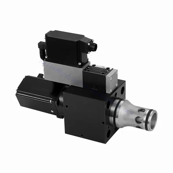
Υδραυλική βαλβίδα ροής υψηλής απόκρισης 2 και 3 κατευθύνσεων σειράς WRCE
Ως ένας από τους κατασκευαστές, προμηθευτές και εξαγωγείς υδραυλικών κυλίνδρων μηχανικών προϊόντων, προσφέρουμε υδραυλικούς κυλίνδρους και πολλά άλλα προϊόντα.
Παρακαλούμε επικοινωνήστε μαζί μας για λεπτομέρειες.
Ταχυδρομείο:sales@hydraulic-cylinders.net
Κατασκευαστής προμηθευτής εξαγωγέας υδραυλικών κυλίνδρων.
Υδραυλική βαλβίδα ροής υψηλής απόκρισης 2 και 3 κατευθύνσεων σειράς WRCE
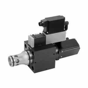
The WRCE series 2- and 3-way high-response flow hydraulic valve is a remarkable hydraulic component designed to deliver exceptional performance in fluid control applications. With its high-response flow capabilities, this valve revolutionizes hydraulic systems by providing precise and efficient flow control.
The WRCE series 2- and 3-way high-response flow hydraulic valve sets new standards in flow control precision and efficiency. With its high-response flow capabilities, compact design, and versatility, this valve empowers hydraulic systems to achieve optimal performance and energy efficiency. By following the recommended usage methods and maintenance guidelines, you can harness the full potential of the WRCE series valve and experience enhanced control and productivity in your hydraulic applications. Upgrade your hydraulic system today and unlock the advantages of efficiency and precision with the WRCE series 2- and 3-way high-response flow hydraulic valve.
WRCE Series 2-and 3-way High-response Flow Hydraulic Valve Key Characteristics:
- High-Response Flow:
- The WRCE series valve is engineered to offer high-response flow control, ensuring rapid and accurate adjustments to fluid flow rates.
- This characteristic enables precise control over hydraulic actuators, resulting in enhanced system performance, reduced energy consumption, and improved overall efficiency.
- Versatile 2- and 3-Way Configuration:
- This valve is available in both 2-way and 3-way configurations, providing flexibility to meet various hydraulic system requirements.
- The 2-way configuration allows for simple on/off control, while the 3-way design enables directional control, making it ideal for applications such as actuator extension and retraction.
- Συμπαγής σχεδιασμός:
- The WRCE series valve features a compact design, making it suitable for installations where space is limited.
- This compact size allows easy integration into various hydraulic systems without compromising performance or functionality.
- High-Pressure Rating:
- This valve is built to withstand high-pressure environments, ensuring reliable operation even in demanding hydraulic applications.
- Its robust construction and high-pressure rating make it suitable for use in systems that require efficient flow control under extreme operating conditions.
WRCE Series 2-and 3-way High-response Flow Hydraulic Valve Parameter:
| Γενικός | |||||
| NS NG | 32 | 40 | 50 | ||
| Βάρος | κιλά | 11.2 | 17.3 | 24.6 | |
| Weight with shut-off valve …../…WK or …/…WL… | κιλά | 12.5 | 18.6 | 25.9 | |
| Size of the pilot control valve (pilot) | NG | 6 | 6 | 6 | |
| Θέση εγκατάστασης | Any, preferably horizontal | ||||
| Storage temperature range | ℃ | –20 to +80 | |||
| Εύρος θερμοκρασίας περιστάσεων | ℃ | –20 to +50 | |||
| Hydraulic (measured with HLP32, ϑoil=40℃ ±5℃) | |||||
| Μέγιστη λειτουργούσα πίεση | – Main stagePort A、B | μπαρ | NS 32~40: 350,NS 50: 420 | ||
| – Pilot control valve port X | 315 | ||||
| – Pilot control valve port Y | 210 | ||||
| Rated flow Δp=5bar | – Specifications …S…L (linear) | Λ/λεπτό | 800 | 1200 | 2000 |
| – Specifications …S…R (linear with progressive fine control range) | 600 | 850 | 1400 | ||
| Nominal flow of pilot valve at Δp=70bar | Λ/λεπτό | 12 | 40 | 40 | |
| Leakage of pilot valve at P=100bar | Λ/λεπτό | 0.3 | 0.7 | 0.7 | |
| Hydraulic fluid | Mineral oil (HL,HLP) to DIN 51524 | ||||
| Hydraulic fluid temperature range | ℃ | 20 to +80;preferably +40 to +50 | |||
| Εύρος ιξώδους | χιλ.2/μικρό | 20 to 380;preferably 30 to 45 | |||
| Maximum admissible degree of contamination of the hydraulic fluid, cleanliness class according to ISO 4406 (c) | Class 20/18/15 | ||||
| Υστέρηση | % | ≤ 0.2 | |||
| Υστέρηση | % | ≤ 0.1 | |||
| Ευαισθησία απόκρισης | % | ≤ 0.1 | |||
| Response Time(step signa 0 ~ 100%) | ms | ≤ 20 | |||
| Ηλεκτρικά δεδομένα | |||||
| Τύπος τάσης | Direct voltage | ||||
| Type of signal | Analog | ||||
| Opening point calibration | % | ≦ 1 | |||
| Zero shift upon change of: | – Hydraulic fluid temperature | %/10K | ≦ 0.3 | ≦ 0.3 | ≦ 0.3 |
| – Pilot pressure in X | %/100bar | ≦ 0.7 | ≦ 0.7 | ≦ 0.7 | |
| – Return flow pressure in Y | %/bar | ≦ 0.3 | ≦ 0.3 | ≦ 0.3 | |
| The protection class of the valve according to EN60529 | IP65 with a mating connector mounted and locked | ||||
WRCE Series 2-and 3-way High-response Flow Hydraulic Valve Advantages:
• Pilot-operated two-stage cartridge high-frequency response throttle valve
• Suitable for closed-loop control of position, pressure, force and speed
• Pilot control valve: six-port direct-acting high-frequency response proportional valve with electric feedback
• Main stage: closed loop position control
• Integrated open loop and closed loop control electronics (OBE)
Usage Method Of WRCE Series 2-and 3-way High-response Flow Hydraulic Valve :
- System Assessment:
- Evaluate your hydraulic system and determine the specific flow control requirements.
- Identify whether the WRCE series valve is compatible with your system based on factors such as flow rates, pressure ratings, and the desired control functions.
- Επιλογή βαλβίδας:
- Select the appropriate variant of the WRCE series valve based on your system parameters and flow control needs.
- Consider factors such as flow capacity, pressure rating, response time, and compatibility with your specific application.
- Εγκατάσταση:
- Follow the manufacturer’s installation instructions carefully to ensure proper alignment and secure mounting of the valve.
- Make sure to create leak-free connections by using suitable hydraulic fittings, adapters, and seals. Tighten the connections adequately to prevent any fluid leaks.
- Ενσωμάτωση σήματος ελέγχου:
- Connect the control signal lines of the valve to a suitable control device, such as a hydraulic control module, electronic control unit, or manual control lever.
- Ensure proper wiring and compatibility between the valve and control device to achieve accurate and responsive flow control.
How To Hook Up Hydraulic Control Valve?
To hook up a hydraulic control valve, follow these steps:
- Identify Valve Type: Determine the specific type of hydraulic control valve you are working with, such as a directional control valve, pressure control valve, or flow control valve. Ensure that the valve is suitable for your application and compatible with your hydraulic system.
- Gather Required Tools and Materials: Collect the necessary tools and materials, including appropriate hydraulic fittings, adapters, hoses, and wrenches. Refer to the manufacturer’s instructions for any specific tools or components needed.
- Προετοιμασία του υδραυλικού συστήματος: Απενεργοποιήστε το υδραυλικό σύστημα και εκτονώστε την πίεση ενεργοποιώντας τη βαλβίδα εκτόνωσης ή ανασύροντας τους υδραυλικούς κυλίνδρους. Αυτό το βήμα είναι κρίσιμο για την ασφάλεια και αποτρέπει την τυχαία κίνηση ή την απελευθέρωση υδραυλικού υγρού.
- Identify Flow Direction: Determine the flow direction in your hydraulic system. Typically, the flow direction is indicated by arrows on the hydraulic components. Ensure that you understand the correct flow direction before proceeding.
- Locate Installation Point: Identify the optimal location to install the hydraulic control valve in your hydraulic system. Consider factors such as accessibility, proximity to the actuator or hydraulic component, and ease of operation. Ensure there is enough space for the valve to be mounted securely.
- Τοποθετήστε τη βαλβίδα: Securely mount the hydraulic control valve in the chosen location using appropriate brackets or clamps. Ensure the valve is positioned correctly, aligning the inlet and outlet ports with the flow direction. Follow the manufacturer’s instructions for the specific mounting requirements of your valve.
- Συνδέστε τις θύρες εισόδου και εξόδου: Attach hydraulic hoses or tubing to the inlet and outlet ports of the hydraulic control valve. Use suitable hydraulic fittings and adapters to create a leak-free connection. Tighten the connections using wrenches to ensure a secure fit, but avoid over-tightening.
- Connect Control Lines: If your hydraulic control valve requires external control signals, connect the control lines from the control device, such as a joystick, lever, or solenoid, to the appropriate ports on the valve. Follow the manufacturer’s instructions for the correct wiring or connection configuration.
- Δοκιμάστε το σύστημα: Once the hydraulic control valve is installed, slowly restore hydraulic system pressure. Test the system to ensure that the valve is functioning correctly. Operate the control device and observe the response of the hydraulic components to verify that the valve is controlling the flow, pressure, or direction as intended.
- Fine-tune and Adjust: Make any necessary adjustments to the hydraulic control valve to achieve the desired flow, pressure, or direction control. Refer to the manufacturer’s instructions for specific adjustment procedures. Regularly monitor the system for any leaks, pressure inconsistencies, or abnormal behavior.
Ικανότητα & χωρητικότητα του εργοστασίου:
(1) Συναρμολόγηση
Διαθέτουμε μια πρώτης τάξεως ανεξάρτητη πλατφόρμα συναρμολόγησης έρευνας και ανάπτυξης. Το εργαστήριο παραγωγής υδραυλικών κυλίνδρων διαθέτει τέσσερις ημιαυτόματες γραμμές συναρμολόγησης ανυψωτικών κυλίνδρων και μία αυτόματη γραμμή συναρμολόγησης κυλίνδρων κλίσης, με σχεδιασμένη ετήσια παραγωγική ικανότητα 1 εκατομμυρίου τεμαχίων. Το εργαστήριο ειδικών κυλίνδρων είναι εξοπλισμένο με διάφορες προδιαγραφές ενός ημιαυτόματου συστήματος συναρμολόγησης καθαρισμού με σχεδιασμένη ετήσια παραγωγική ικανότητα 200.000 και εξοπλισμένο με διάσημο εξοπλισμό κατεργασίας CNC, ένα κέντρο κατεργασίας, έναν ειδικό εξοπλισμό επεξεργασίας κυλίνδρων υψηλής ακρίβειας, μια μηχανή συγκόλλησης ρομπότ, μια αυτόματη μηχανή καθαρισμού, μια αυτόματη μηχανή συναρμολόγησης κυλίνδρων και μια αυτόματη γραμμή παραγωγής βαφής. Υφιστάμενος κρίσιμος εξοπλισμός άνω των 300 σετ (σετ). Η βέλτιστη κατανομή και η αποτελεσματική χρήση των πόρων του εξοπλισμού διασφαλίζουν τις απαιτήσεις ακρίβειας των προϊόντων και καλύπτουν τις ανάγκες υψηλής ποιότητας των προϊόντων.


(2) Κατεργασία
Το εργαστήριο κατεργασίας είναι εξοπλισμένο με ένα προσαρμοσμένο κέντρο τόρνευσης με κεκλιμένη ράγα, κέντρο κατεργασίας, μηχανή λείανσης υψηλής ταχύτητας, ρομπότ συγκόλλησης και άλλο συναφή εξοπλισμό, το οποίο μπορεί να χειριστεί την επεξεργασία κυλινδρικών σωλήνων με μέγιστη εσωτερική διάμετρο 400 mm και μέγιστο μήκος 6 μέτρων.

(3) Συγκόλληση

(4) Βαφή και επίστρωση
Με μικρές και μεσαίες αυτόματες γραμμές επίστρωσης χρωμάτων με βάση το νερό, για την επίτευξη αυτόματης φόρτωσης και εκφόρτωσης ρομπότ και αυτόματου ψεκασμού, η ικανότητα σχεδιασμού 4000 τεμαχίων ανά βάρδια,
Διαθέτουμε επίσης μια ημιαυτόματη γραμμή παραγωγής χρωμάτων για μεγάλους κυλίνδρους που τροφοδοτείται από μια αλυσίδα ισχύος, με δυνατότητα σχεδιασμού 60 κιβωτίων ανά βάρδια.


(5) Δοκιμές
Διαθέτουμε πρώτης τάξεως εγκαταστάσεις επιθεώρησης και δοκιμαστικές κλίνες για να διασφαλίσουμε ότι η απόδοση του κυλίνδρου ανταποκρίνεται στις απαιτήσεις.

Είμαστε ένας από τους καλύτερους κατασκευαστές υδραυλικών κυλίνδρων. Μπορούμε να προσφέρουμε ολοκληρωμένους υδραυλικούς κυλίνδρους. Παρέχουμε επίσης αντίστοιχους γεωργικά κιβώτια ταχυτήτων. Έχουμε εξάγει τα προϊόντα μας σε πελάτες σε όλο τον κόσμο και έχουμε κερδίσει μια καλή φήμη λόγω της ανώτερης ποιότητας των προϊόντων μας και της εξυπηρέτησης μετά την πώληση. Καλωσορίζουμε τους πελάτες στο εσωτερικό και στο εξωτερικό να επικοινωνήσουν μαζί μας για να διαπραγματευτούν τις επιχειρήσεις, να ανταλλάξουν πληροφορίες και να συνεργαστείτε μαζί μας!
Υδραυλικός κύλινδρος Εφαρμογή:
