
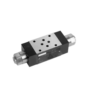
Υδραυλική βαλβίδα ελέγχου ροής σειράς Z2FRM
Ως ένας από τους κατασκευαστές, προμηθευτές και εξαγωγείς υδραυλικών κυλίνδρων μηχανικών προϊόντων, προσφέρουμε υδραυλικούς κυλίνδρους και πολλά άλλα προϊόντα.
Παρακαλούμε επικοινωνήστε μαζί μας για λεπτομέρειες.
Ταχυδρομείο:sales@hydraulic-cylinders.net
Κατασκευαστής προμηθευτής εξαγωγέας υδραυλικών κυλίνδρων.
Υδραυλική βαλβίδα ελέγχου ροής σειράς Z2FRM
The Z2FRM series flow control hydraulic valve is a state-of-the-art hydraulic component designed to revolutionize the control and efficiency of hydraulic systems. With its advanced features and exceptional performance, this valve provides precise flow control and enhances the overall productivity of hydraulic machinery.
The Z2FRM series flow control hydraulic valve is a game-changing solution for precise flow control in hydraulic systems. With its unmatched precision, versatility, and durability, this valve empowers operators to optimize the performance and efficiency of their hydraulic machinery. By following the recommended usage methods and maintenance guidelines, you can unlock the full potential of the Z2FRM series flow control hydraulic valve, ensuring seamless operation and reliable flow control in your hydraulic applications. Upgrade your hydraulic system today and experience the power of precise hydraulic control with the Z2FRM series valve.
Z2FRM Series Flow Control Hydraulic Valve Key Characteristics:
- Precision Flow Control:
- The Z2FRM series valve offers unparalleled precision in controlling the flow rate of hydraulic fluids, allowing for fine-tuned adjustments and optimized performance.
- With its high accuracy, this valve ensures consistent flow control, resulting in enhanced system efficiency and improved productivity.
- Ευέλικτες εφαρμογές:
- The Z2FRM series valve is highly versatile and compatible with a wide range of hydraulic systems, including industrial machinery, construction equipment, and mobile applications.
- Its adaptability makes it an ideal choice for diverse hydraulic setups, providing reliable and efficient flow control.
- Σταθερότητα πίεσης και θερμοκρασίας:
- Engineered to withstand varying pressure and temperature conditions, the Z2FRM series valve maintains stable flow control even in demanding operational environments.
- It ensures consistent performance, minimizes flow fluctuations, and safeguards the integrity of the hydraulic system.
- Στιβαρή κατασκευή:
- The Z2FRM Series Valve boasts a robust design and is crafted from high-quality materials, guaranteeing durability and long-lasting reliability.
- Its sturdy construction enables it to withstand high pressures, vibrations, and extreme temperatures, making it a dependable solution for critical hydraulic applications.
Z2FRM Series Flow Control Hydraulic Valve Parameter:
NG6
| Βαλβίδα ελέγχου ροής | |||||||||||
| Μέγιστη λειτουργούσα πίεση-Θύρα Α | μπαρ | 315 | |||||||||
| Διαφορική πίεση ΔP για ελεύθερη ροή επιστροφής Β προς Α | Δείτε χαρακτηριστικές καμπύλες | ||||||||||
| Ελάχιστη διαφορά πίεσης | μπαρ | 6 έως 14 | |||||||||
| Σταθερότητα πίεσης έως P= 315 bar | % | ±2 (Qmax) | |||||||||
| Ροή | Qmax | Λ/λεπτό | 0.2 | 0.6 | 1.5 | 3 | 6 | 10 | 16 | 25 | 32 |
| Qmin έως 100bar | mL/λεπτό | 15 | 15 | 15 | 15 | 25 | 50 | 70 | 100 | 250 | |
| Qmin έως 315bar | 25 | 25 | 25 | 25 | 25 | 50 | 70 | 100 | 250 | ||
| Υγρό | Ορυκτέλαιο, φωσφορικός εστέρας | ||||||||||
| Εύρος θερμοκρασίας ρευστού | ℃ | – 20 έως + 80 | |||||||||
| Εύρος ιξώδους | mm2/s | 10 έως 800 | |||||||||
| Βαθμός μόλυνσης | Μέγιστος επιτρεπόμενος βαθμός μόλυνσης υγρού: Κλάση 9. NAS 1638 ή 20/18/15, ISO4406 | ||||||||||
| Θέση εγκατάστασης | Προαιρετικός | ||||||||||
| Εύρος θερμοκρασίας περιστάσεων | ℃ | -20 έως +50 | |||||||||
| Βάρος | 2FRM6A…2FRM6B… | κιλά | περίπου 1,3 | ||||||||
| 2FRM6SB… | κιλά | περίπου 1,5 | |||||||||
| Διορθωτής | |||||||||||
| Ονομαστική ροή | μπαρ | 320 | |||||||||
| Μέγιστη λειτουργούσα πίεση | μπαρ | έως 210 | |||||||||
| Πίεση ρωγμών | μπαρ | 0.7 | |||||||||
| Βάρος | κιλά | περίπου 0,9 | |||||||||
NG5/10/16
| Βαλβίδα ελέγχου ροής | ||||||||||||||||
| Μέγιστη λειτουργούσα πίεση-Θύρα Α | μπαρ | 315 | ||||||||||||||
| Διαφορική πίεση ΔP για ελεύθερη ροή επιστροφής Β προς Α | Δείτε χαρακτηριστικές καμπύλες | |||||||||||||||
| Ελάχιστη διαφορά πίεσης | μπαρ | 6 έως 14 | ||||||||||||||
| Υγρό | Ορυκτέλαιο, φωσφορικός εστέρας | |||||||||||||||
| Εύρος θερμοκρασίας ρευστού | ℃ | – 20 έως + 80 | ||||||||||||||
| Εύρος ιξώδους | mm2/s | 10 έως 800 | ||||||||||||||
| Βαθμός μόλυνσης | Μέγιστος επιτρεπόμενος βαθμός μόλυνσης υγρού: Κλάση 9. NAS 1638 ή 20/18/15, ISO4406 | |||||||||||||||
| Μέγεθος | χιλ. | 5 | 10 | 16 | ||||||||||||
| Μέγιστος ρυθμός ροής | Λ/λεπτό | 0.2 | 0.6 | 1.2 | 3 | 6 | 10 | 15 | 10 | 16 | 25 | 50 | 60 | 100 | 160 | |
| Ροή επιστροφής λαδιού Β προς Α | mL/λεπτό | 0.5 | 0.5 | 0.6 | 0.9 | 1.8 | 3.6 | 6.7 | 2 | 2.5 | 3.5 | 6 | 2.8 | 4.3 | 7.3 | |
| σταθερό εύρος ροής (%Qmax) (-20-±80℃) | ±5 | ±3 | ±2 | ±2 | ||||||||||||
| ±2 (P=210 bar) | ±2 (P=350 bar) | |||||||||||||||
| Πίεση εργασίας | μπαρ | 210 | 350 | |||||||||||||
| Ελάχιστη πτώση πίεσης | μπαρ | 3-5 | 6-8 | 3-7 | 5-12 | |||||||||||
| Βάρος | κιλά | 1.6 | 3.4 | 7.4 | ||||||||||||
| Διορθωτής | ||||||||||||||||
| Υγρό | Ορυκτέλαιο, φωσφορικός εστέρας | |||||||||||||||
| Εύρος θερμοκρασίας ρευστού | -20 έως +80 | |||||||||||||||
| Εύρος ιξώδους | 10 έως 800 | |||||||||||||||
| Βαθμός μόλυνσης | Μέγιστος επιτρεπόμενος βαθμός μόλυνσης υγρού: Κλάση 9. NAS 1638 ή 20/18/15, ISO4406 | |||||||||||||||
| Μέγεθος | 5 | 10 | 16 | |||||||||||||
| Ροή | 15 | 50 | 160 | |||||||||||||
| Πίεση εργασίας | 210 | 315 | 315 | |||||||||||||
| Πίεση ρωγμών | 1 | 1.5 | 1.5 | |||||||||||||
| Βάρος | 0.6 | 3.2 | 9.3 | |||||||||||||
Z2FRM Series Flow Control Hydraulic Valve Advantages:
• Τοποθέτηση βάσης υποπλάκας, δείτε τον κατάλογο προϊόντων
• Περιοριστής μετατόπισης αντιστάθμισης πίεσης, προαιρετικός
• Προαιρετική βαλβίδα μίας κατεύθυνσης
• Κουμπί με κλίμακα, προαιρετική δυνατότητα κλειδώματος
Usage Method Of Z2FRM Series Flow Control Hydraulic Valve:
- Αξιολόγηση Συστήματος:
- Begin by assessing the specific requirements of your hydraulic system, including desired flow rates, pressure ranges, and flow control parameters.
- Determine if the Z2FRM series valve suits your application based on its flow control capabilities and compatibility with your system.
- Επιλογή βαλβίδας:
- Select the appropriate variant of the Z2FRM series valve based on your system parameters, desired flow rate, and compatibility with other system components.
- Λάβετε υπόψη παράγοντες όπως η μέγιστη χωρητικότητα ροής, η ονομαστική πίεση και οι συνθήκες λειτουργίας.
- Εγκατάσταση:
- Follow the manufacturer’s installation instructions meticulously, ensuring precise alignment and secure valve connections.
- Pay close attention to the flow direction indicators, ensuring the correct positioning of the valve within the hydraulic system.
- Ρύθμιση ελέγχου ροής:
- Once installed, adjust the flow control settings of the valve to achieve the desired flow rate and meet your system requirements.
- Fine-tune the valve to optimize the speed and performance of hydraulic actuators, thereby maximizing overall system efficiency.
How To Add A Hydraulic Valve To A Tractor?
Adding a hydraulic valve to a tractor can expand its functionality and enable the use of hydraulic attachments and implements. Here are the general steps to follow when adding a hydraulic valve to a tractor:
- Determine the Tractor’s Hydraulic System:
- Check if your tractor already has a hydraulic system in place. Many modern tractors come equipped with hydraulic systems, while older models may require modifications or additional components.
- Choose the Right Hydraulic Valve:
- Select a hydraulic valve that suits your specific needs and requirements. Consider factors such as flow rate, pressure rating, number of spools, and compatibility with your tractor’s hydraulic system.
- Συγκεντρώστε τα απαραίτητα εργαλεία και υλικά:
- Ensure you have all the required tools and materials for the installation process. This may include wrenches, hydraulic hoses, fittings, mounting brackets, and the hydraulic valve itself.
- Identify the Installation Location:
- Determine the ideal location for mounting the hydraulic valve on your tractor. This is typically near the existing hydraulic ports or in a convenient and accessible position.
- Prepare the Tractor:
- Before installation, shut off the tractor’s engine and relieve any pressure in the hydraulic system by moving the hydraulic control levers back and forth.
- Install the Hydraulic Valve:
- Mount the hydraulic valve securely using the appropriate brackets or mounting hardware. Ensure it is positioned correctly and aligned with the hydraulic ports.
- Connect the Hydraulic Hoses:
- Attach hydraulic hoses to the valve’s ports, ensuring a secure connection. Use appropriate fittings and tighten them properly to prevent leaks.
- Connect to the Tractor’s Hydraulic System:
- Identify the tractor’s existing hydraulic ports or couplers. Connect the hydraulic hoses from the valve to these ports, matching the appropriate fittings.
- Δοκιμή για διαρροές:
- Once all connections are made, start the tractor’s engine and operate the hydraulic controls. Carefully inspect all connections for any signs of hydraulic fluid leaks. Address any leaks promptly by tightening fittings or replacing damaged components.
- Test the Hydraulic Valve:
- Engage the hydraulic controls and test the operation of the newly installed hydraulic valve. Ensure that it functions smoothly and controls the hydraulic attachments as intended.
- Secure and Protect the Hoses:
- Secure the hydraulic hoses in place using clamps or brackets to prevent them from interfering with other tractor components or getting damaged during operation. Consider using protective covers for the hoses to safeguard them from environmental elements and potential abrasion.
Ικανότητα & χωρητικότητα του εργοστασίου:
(1) Συναρμολόγηση
Διαθέτουμε μια πρώτης τάξεως ανεξάρτητη πλατφόρμα συναρμολόγησης έρευνας και ανάπτυξης. Το εργαστήριο παραγωγής υδραυλικών κυλίνδρων διαθέτει τέσσερις ημιαυτόματες γραμμές συναρμολόγησης ανυψωτικών κυλίνδρων και μία αυτόματη γραμμή συναρμολόγησης κυλίνδρων κλίσης, με σχεδιασμένη ετήσια παραγωγική ικανότητα 1 εκατομμυρίου τεμαχίων. Το εργαστήριο ειδικών κυλίνδρων είναι εξοπλισμένο με διάφορες προδιαγραφές ενός ημιαυτόματου συστήματος συναρμολόγησης καθαρισμού με σχεδιασμένη ετήσια παραγωγική ικανότητα 200.000 και εξοπλισμένο με διάσημο εξοπλισμό κατεργασίας CNC, ένα κέντρο κατεργασίας, έναν ειδικό εξοπλισμό επεξεργασίας κυλίνδρων υψηλής ακρίβειας, μια μηχανή συγκόλλησης ρομπότ, μια αυτόματη μηχανή καθαρισμού, μια αυτόματη μηχανή συναρμολόγησης κυλίνδρων και μια αυτόματη γραμμή παραγωγής βαφής. Υφιστάμενος κρίσιμος εξοπλισμός άνω των 300 σετ (σετ). Η βέλτιστη κατανομή και η αποτελεσματική χρήση των πόρων του εξοπλισμού διασφαλίζουν τις απαιτήσεις ακρίβειας των προϊόντων και καλύπτουν τις ανάγκες υψηλής ποιότητας των προϊόντων.


(2) Κατεργασία
Το εργαστήριο κατεργασίας είναι εξοπλισμένο με ένα προσαρμοσμένο κέντρο τόρνευσης με κεκλιμένη ράγα, κέντρο κατεργασίας, μηχανή λείανσης υψηλής ταχύτητας, ρομπότ συγκόλλησης και άλλο συναφή εξοπλισμό, το οποίο μπορεί να χειριστεί την επεξεργασία κυλινδρικών σωλήνων με μέγιστη εσωτερική διάμετρο 400 mm και μέγιστο μήκος 6 μέτρων.

(3) Συγκόλληση

(4) Βαφή και επίστρωση
Με μικρές και μεσαίες αυτόματες γραμμές επίστρωσης χρωμάτων με βάση το νερό, για την επίτευξη αυτόματης φόρτωσης και εκφόρτωσης ρομπότ και αυτόματου ψεκασμού, η ικανότητα σχεδιασμού 4000 τεμαχίων ανά βάρδια,
Διαθέτουμε επίσης μια ημιαυτόματη γραμμή παραγωγής χρωμάτων για μεγάλους κυλίνδρους που τροφοδοτείται από μια αλυσίδα ισχύος, με δυνατότητα σχεδιασμού 60 κιβωτίων ανά βάρδια.


(5) Δοκιμές
Διαθέτουμε πρώτης τάξεως εγκαταστάσεις επιθεώρησης και δοκιμαστικές κλίνες για να διασφαλίσουμε ότι η απόδοση του κυλίνδρου ανταποκρίνεται στις απαιτήσεις.

Είμαστε ένας από τους καλύτερους κατασκευαστές υδραυλικών κυλίνδρων. Μπορούμε να προσφέρουμε ολοκληρωμένους υδραυλικούς κυλίνδρους. Παρέχουμε επίσης αντίστοιχους γεωργικά κιβώτια ταχυτήτων. Έχουμε εξάγει τα προϊόντα μας σε πελάτες σε όλο τον κόσμο και έχουμε κερδίσει μια καλή φήμη λόγω της ανώτερης ποιότητας των προϊόντων μας και της εξυπηρέτησης μετά την πώληση. Καλωσορίζουμε τους πελάτες στο εσωτερικό και στο εξωτερικό να επικοινωνήσουν μαζί μας για να διαπραγματευτούν τις επιχειρήσεις, να ανταλλάξουν πληροφορίες και να συνεργαστείτε μαζί μας!
Υδραυλικός κύλινδρος Εφαρμογή:
