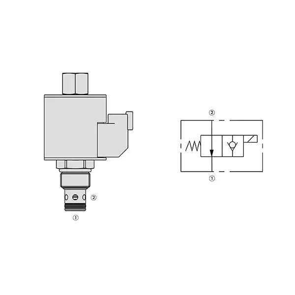
Válvula direccional solenoide 30SD10-21
Como cilindros hidráulicos uno de los fabricantes, los surtidores y los exportadores de productos mecánicos, ofrecemos cilindros hidráulicos y muchos otros productos.
Póngase en contacto con nosotros para más información.
Correo:sales@hydraulic-cylinders.net
Fabricante proveedor exportador de cilindros hidráulicos.
Válvula direccional solenoide 30SD10-21

The 30SD10-21 solenoid directional valve is a high-performance component that optimizes fluid control in various industrial applications. With its advanced features, precise operation, and reliable performance, this solenoid valve offers exceptional functionality and efficiency, making it a valuable asset for fluid control systems. From manufacturing to automation, the 30SD10-21 solenoid directional valve delivers precise and reliable fluid control, empowering industries to enhance productivity and streamline operations.
The 30SD10-21 solenoid directional valve is a versatile and reliable component that enhances fluid control efficiency in industrial applications. With its robust construction, precise fluid control, versatility, and reliable performance, this solenoid valve offers exceptional functionality, ensuring optimal operations and increased productivity. By incorporating the 30SD10-21 solenoid directional valve into fluid control systems, industries can achieve enhanced efficiency, accuracy, and system performance. Invest in this advanced solenoid valve to streamline your fluid control processes, improve productivity, and gain a competitive edge in your industry.
30SD10-21 Solenoid Directional Valve Characteristics:
- Robust Construction: The 30SD10-21 solenoid directional valve is built robustly, ensuring durability and longevity even in demanding environments. Its sturdy construction allows it to withstand high pressures, temperature variations, and harsh conditions, providing consistent and reliable performance.
- Precise Fluid Control: This solenoid valve offers precise control over fluid flow, allowing for accurate regulation and efficient management of liquids or gases. With its responsive solenoid mechanism, the valve enables quick and reliable switching between different flow paths, ensuring precise control and minimizing disruptions.
- Versatile Functionality: The 30SD10-21 solenoid directional valve offers versatile functionality, making it suitable for various applications. Whether directional control, on/off switch, or pressure regulation, this valve can be tailored to meet specific system requirements, providing flexibility and adaptability in fluid control systems.
- Reliable Performance: This solenoid valve is designed for reliable performance, ensuring consistent and efficient fluid control operations. Its high-quality components and precision engineering contribute to its reliability, allowing for smooth and trouble-free operation even in critical applications.
30SD10-21 Solenoid Directional Valve Parameter:
| Presión nominal | 241 bares (3500 psi) | |
| Flujo máximo | 56,8 L/min (15 gpm); Ver tabla de rendimiento | |
| Líquido | De base mineral o sintética con propiedades lubricantes | |
| Rango de temperatura del fluido ℃ | -54 a 107 ℃ (Sellos de poliuretano) | |
| -40 a 100 ℃ (sellos Buna N) | ||
| -26 a 204 ℃ (sellos de fluorocarbono) | ||
| Rango de viscosidad | 7,4 a 420 mm2/s | |
| Grado de contaminación | El nivel mínimo de contaminación es ISO4406 nivel 18/16/13, y se recomienda el nivel 15/13/11 para prolongar la vida útil. | |
| Fuga interna | ≤ 0,15 mL/min (3 gotas/min) a 241 bar | |
| Cavidad | VC10-2 | |
| Clasificación de servicio de la bobina | Continua desde 85% hasta 115% de tensión nominal | |
| Consumo de corriente inicial de la bobina a 20 ℃ | Bobina electrónica | 1,7 A a 12 V CC; 0,85 A a 24 V CC |
| Bobina D | 1,67 A a 12 V CC; 0,83 A a 24 V CC | |
| Tensión mínima de entrada | 85% de nominal a 241 bar | |
30SD10-21 Solenoid Directional Valve Advantages:
• Bobina con clasificación de servicio continuo
• Construcción eficiente de armadura húmeda
• Los cartuchos son intercambiables en voltaje.
• Bobinas E impermeables opcionales con clasificación hasta IP69K
• Cavidad común en la industria
• Piezas endurecidas para una mayor vida útil y bajas fugas
Usage Method Of 30SD10-21 Solenoid Directional Valve:
Instalación:
- Follow the manufacturer’s instructions for properly installing the 30SD10-21 Solenoid Directional Valve.
- Ensure accurate alignment and connection to the fluid control system, using appropriate fittings and seals to maintain a leak-free operation.
Conexiones eléctricas:
- Connect the solenoid valve to the power supply, adhering to the specified voltage and electrical requirements.
- Asegúrese de que el cableado y el aislamiento sean adecuados para garantizar un funcionamiento eléctrico seguro y confiable.
Dirección del flujo del fluido:
- Determine the desired fluid flow direction based on the application requirements.
- The 30SD10-21 solenoid directional valve provides various ports and positions for inlet, outlet, and exhaust. Refer to the product documentation for correct port connections.
Señal de control:
- Conecte la señal de control, ya sea eléctrica o neumática, a la válvula solenoide para activar su mecanismo de conmutación.
- Ensure that the control signal is compatible with the valve’s specifications and operating parameters.
¿Cómo conectar una válvula de control de flujo hidráulico?
Para conectar una válvula de control de flujo hidráulico, siga estos pasos:
- Identificar el tipo de válvula: Determine el tipo específico de válvula de control de flujo con la que trabaja. Los tipos más comunes incluyen válvulas de aguja, válvulas de control de flujo ajustables o válvulas de control de flujo con compensación de presión. Asegúrese de que la válvula sea adecuada para su aplicación y compatible con su sistema hidráulico.
- Reúna las herramientas y los materiales necesarios: Reúna las herramientas y los materiales necesarios, incluidos accesorios hidráulicos, adaptadores, mangueras y llaves inglesas adecuadas.
- Prepare el sistema hidráulico: Apague el sistema hidráulico y libere la presión activando la válvula de alivio o retrayendo los cilindros hidráulicos. Este paso es crucial para la seguridad.
- Identificar la dirección del flujo: Identifique la dirección del flujo en su sistema hidráulico. Normalmente, la dirección del flujo se indica mediante flechas en los componentes hidráulicos. Asegúrese de comprender la dirección correcta del flujo antes de continuar.
- Localizar el punto de instalación: Determine la ubicación óptima para instalar la válvula de control de flujo en su sistema hidráulico. Considere factores como la accesibilidad, la proximidad al actuador o componente hidráulico y la facilidad de ajuste.
- Monte la válvula: Monte firmemente la válvula de control de flujo en la ubicación elegida utilizando los soportes o abrazaderas adecuados. Asegúrese de que la válvula esté correctamente colocada, alineando los puertos de entrada y salida con la dirección del flujo.
- Conecte los puertos de entrada y salida: Conecte mangueras o tubos hidráulicos a los puertos de entrada y salida de la válvula de control de flujo. Utilice accesorios y adaptadores hidráulicos adecuados para lograr una conexión sin fugas. Apriete las conexiones con llaves para asegurar un ajuste firme, pero evite apretarlas demasiado.
- Ajuste el control de flujo: Depending on the type of flow control valve, it may have adjustable features such as a needle valve or a flow control knob. Adjust the valve according to your desired flow rate or speed. Refer to the manufacturer’s instructions for specific adjustment procedures.
- Pruebe el sistema: Una vez instalada y ajustada la válvula de control de flujo, restablezca lentamente la presión del sistema hidráulico. Pruebe el sistema para asegurar que la válvula de control de flujo funcione correctamente. Supervise el caudal o la velocidad del actuador hidráulico para verificar que se encuentre dentro del rango deseado.
- Ajuste fino y monitorización: Ajuste la válvula de control de flujo para alcanzar el caudal o la velocidad deseados. Revise periódicamente el sistema hidráulico para detectar fugas, inconsistencias de presión o comportamiento inusual.
Capacidad de la fábrica:
(1) Montaje
Contamos con una plataforma de ensamblaje independiente de primera clase para investigación y desarrollo. El taller de producción de cilindros hidráulicos cuenta con cuatro líneas de ensamblaje de cilindros de elevación semiautomáticos y una línea de ensamblaje de cilindros de inclinación automáticos, con una capacidad de producción anual diseñada de 1 millón de piezas. El taller de cilindros especiales está equipado con un sistema de ensamblaje de limpieza semiautomático de diversas especificaciones, con una capacidad de producción anual diseñada de 200,000 unidades, y está equipado con reconocidos equipos de mecanizado CNC, un centro de mecanizado, equipos especiales de procesamiento de cilindros de alta precisión, una máquina de soldadura robotizada, una máquina de limpieza automática, una máquina de ensamblaje de cilindros automáticos y una línea de producción de pintura automática. Contamos con más de 300 equipos críticos. La asignación óptima y el uso eficiente de los recursos de equipo garantizan la precisión y la alta calidad de los productos.


(2) Mecanizado
El taller de mecanizado está equipado con un centro de torneado de carril inclinado personalizado, un centro de mecanizado, una máquina de bruñido de alta velocidad, un robot de soldadura y otros equipos relacionados, que pueden procesar tubos cilíndricos con un diámetro interior máximo de 400 mm y una longitud máxima de 6 metros.

(3) Soldadura

(4) Pintura y revestimiento
Con pequeñas y medianas líneas de cilindros automáticos de recubrimiento de pintura a base de agua, para lograr la carga y descarga automática de robots y pulverización automática, la capacidad de diseño de 4000 piezas por turno;
También disponemos de una línea semiautomática de producción de pintura para grandes cilindros accionada por cadena, con una capacidad de diseño de 60 cajas por turno.


(5) Pruebas
Disponemos de instalaciones de inspección y bancos de pruebas de primera clase para garantizar que el rendimiento del cilindro cumple los requisitos.

Somos uno de los mejores fabricantes de cilindros hidráulicos. Ofrecemos cilindros hidráulicos integrales. También proporcionamos... cajas de cambios agrícolasHemos exportado nuestros productos a clientes de todo el mundo y nos hemos ganado una excelente reputación gracias a nuestra excelente calidad y servicio posventa. Invitamos a clientes nacionales e internacionales a contactarnos para negociar negocios, intercambiar información y... colabore con nosotros!
Cilindro hidráulico Aplicación:
