Válvula hidráulica direccional proporcional serie 4WRPEH
Válvula hidráulica direccional proporcional serie 4WRPEH
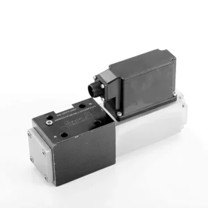
La válvula hidráulica direccional proporcional de la serie 4WRPEH es un componente hidráulico avanzado diseñado para ofrecer precisión y control excepcionales en sistemas hidráulicos. Gracias a su innovadora tecnología de control direccional proporcional, esta válvula permite una regulación precisa del caudal y cambios de dirección suaves.
La válvula hidráulica direccional proporcional de la serie 4WRPEH proporciona a los sistemas hidráulicos un control de caudal preciso, funcionalidad versátil y mayor eficiencia. Su tecnología de control direccional proporcional garantiza un ajuste de caudal preciso y preciso, mientras que su alta capacidad de caudal garantiza un rendimiento fiable incluso en aplicaciones exigentes. Siguiendo las recomendaciones de uso y mantenimiento, podrá maximizar las ventajas y la durabilidad de la válvula de la serie 4WRPEH, elevando su sistema hidráulico a nuevos niveles de precisión y control. Actualice su sistema hidráulico hoy mismo y experimente la potencia de la válvula hidráulica direccional proporcional de la serie 4WRPEH.
Características clave de la válvula hidráulica direccional proporcional serie 4WRPEH:
- Control direccional proporcional:
- La válvula de la serie 4WRPEH utiliza tecnología de control direccional proporcional de última generación, lo que permite un ajuste de flujo preciso y proporcional en función de las señales de control.
- Esta característica garantiza un control preciso y sensible, lo que da como resultado un mejor rendimiento del sistema, un menor consumo de energía y una mayor productividad.
- Funcionalidad versátil:
- Esta válvula ofrece un control versátil sobre la dirección del fluido hidráulico, lo que la hace adecuada para una amplia gama de aplicaciones.
- Permite la activación y desactivación sin problemas de componentes hidráulicos como cilindros, motores y actuadores en diferentes direcciones, mejorando la flexibilidad y adaptabilidad del sistema.
- Alta capacidad de flujo:
- La válvula de la serie 4WRPEH está diseñada para manejar altos caudales, lo que la hace ideal para aplicaciones que requieren una potencia hidráulica sustancial.
- Su construcción robusta garantiza un rendimiento confiable incluso en condiciones exigentes, proporcionando un control de flujo constante y eficiente.
- Medición precisa:
- Con su tecnología de control proporcional, esta válvula ofrece una medición precisa del fluido hidráulico, lo que permite un control y regulación precisos de los caudales.
- Esta precisión mejora el rendimiento general del sistema y garantiza movimientos precisos de los actuadores hidráulicos.
Parámetros de la válvula hidráulica direccional proporcional serie 4WRPEH:
NG6
| General | |||||||
| Diseño | Válvula de carrete, de accionamiento directo, con manguito de acero | ||||||
| Actuación | Solenoide proporcional con control de posición, OBE | ||||||
| Tipo de conexión | Montaje sobre placa, patrón de puertos según ISO 4401-03-02-0-05 | ||||||
| Posición de instalación | Cualquier | ||||||
| Rango de temperatura ambiente | °C | -20…+50 | |||||
| Peso | kilogramo | alrededor de 2,75 | |||||
| Máxima resistencia a la vibración (condición de prueba) | Máx. 25 g, prueba de vibración espacial en todas las direcciones (24 h) | ||||||
| Hidráulico (medido a p=100bar, con HLP46 a ϑoil = 40℃ ±5℃) | |||||||
| Fluido a presión | Aceite mineral (HL, HLP) según DIN 51 524 | ||||||
| Rango de viscosidad | recomendado | mm²/s | 20…100 | ||||
| máximo permitido | mm²/s | 10…800 | |||||
| Rango de temperatura del fluido a presión | °C | -20 a +70 | |||||
| Grado máximo permitido de contaminación del fluido a presión Clase de pureza según ISO 4406 (c) | Clase 18/16/13 | ||||||
| Caudal nominal (Δp = 35 bar por borde) | L/min | 2 | 4 | 12 | 24 | 40 | |
| Presión máxima de funcionamiento | bar | Puerto A, B, P: 315 | |||||
| Presión máxima | bar | Puerto T: 250 | |||||
| Caudal de fuga a 100 bar | Lineal | cm³/min | <150 | <180 | <300 | <500 | <900; |
| No lineal | cm³/min | / | / | / | <300 | <450; | |
| Estático/Dinámico | |||||||
| Histéresis | % | ≤0,2 | |||||
| Tiempo de actuación para el paso de señal 0…100% | EM | 10 | |||||
| Deriva de temperatura | Desplazamiento de cero < 1% a ΔT=40℃ | ||||||
| Compensación cero | De fábrica ±1% | ||||||
| Electrónica de control eléctrica integrada en la válvula. | |||||||
| Ciclo de trabajo relativo | % | 100ED | |||||
| Grado de protección | IP65 | ||||||
| Conexión | Conector enchufable 6P+PE, DIN 43563 | ||||||
| Tensión de alimentación Terminal A Terminal B |
24 VCCnombre | ||||||
| mín. 21 VCC / máx. 40 VCC | |||||||
| 0 V (ondulación máxima 2) | |||||||
| Protección por fusibles, externa | AF | 2.5 | |||||
| entrada, versión “A1” Terminal D (Umi) Terminal E |
Amplificador diferencial, Ri = 100 kΩ | ||||||
| 0…±10 V | |||||||
| 0 V | |||||||
| Entrada, versión “F1” Terminal D (Identificación electrónica) Terminal E (Identificación electrónica) |
Carga, Rella = 200 Ω | ||||||
| 4…12…20 mA | |||||||
| Bucle de corriente IDelaware devolver | |||||||
| Señal de prueba, versión “A1” Terminal F (Prueba de la UT) Terminal C |
LVDT | ||||||
| 0…±10 V | |||||||
| Referencia 0 V | |||||||
| Señal de prueba, versión “F1” Terminal F ( I FC ) Terminal C ( I FC ) |
Señal LVDT 4 … (12) … 20 mA en carga externa 200 … 500 Ωmáximo | ||||||
| 4 … (12) … 20 mA (salida) | |||||||
| Bucle de corriente IFC devolver | |||||||
| Ajuste | Calibrado antes de la entrega, ver curvas características. | ||||||
NG10
| General | |||||
| Diseño | Válvula de carrete, de accionamiento directo, con manguito de acero | ||||
| Actuación | Solenoide proporcional con control de posición, OBE | ||||
| Tipo de conexión | Puerto de placa, patrón de puertos (ISO 4401-05-04-0-05) | ||||
| Posición de instalación | Cualquier | ||||
| Circunstancias rango de temperatura | °C | -20…+50 | |||
| Peso | kilogramo | alrededor de 7.1 | |||
| Máxima resistencia a la vibración (condición de prueba) | Máx. 25 g, prueba de vibración espacial en todas las direcciones (24 h) | ||||
| Hidráulico (medido con HLP 46, ϑoil = 40℃ ± 5℃) | |||||
| Fluido a presión | Aceite hidráulico según DIN 51524…535 | ||||
| Rango de viscosidad | recomendado | mm²/s | 20…100 | ||
| Máx. permitido | mm²/s | 10…800 | |||
| Rango de temperatura del fluido a presión | °C | -20 a +70 | |||
| Grado máximo admisible de contaminación del fluido hidráulico, clase de limpieza según ISO 4406 (c) | Clase 18/16/13 | ||||
| Caudal nominal (Δp = 35 bar por borde) | L/min | 50 | 100 | ||
| Presión máxima de funcionamiento | bar | Puerto PAB: 315 | |||
| Presión máxima | bar | Puerto T: 250 | |||
| Caudal de fuga a 100 bar | Lineal | cm³/min | <1200 | <1500 | |
| No lineal | cm³/min | <600 | <600 | ||
| Estático/Dinámico | |||||
| Histéresis | % | ≤0,2 | |||
| Tiempo de actuación para el paso de señal 0…100% | EM | 25 | |||
| Deriva de temperatura | Desplazamiento de cero < 1% a ΔT=40℃ | ||||
| Compensación cero | De fábrica ±1% | ||||
| Electrónica de control eléctrica integrada en la válvula. | |||||
| Ciclo de trabajo relativo | % | 100ED | |||
| Grado de protección | IP65 (con conector de acoplamiento montado y bloqueado) | ||||
| Conexión | Conector macho 6P+PE, DIN 43563 | ||||
| Tensión de alimentación Terminal A Terminal B |
24 VCCnombre | ||||
| mín. 21 VCC / máx. 40 VCC | |||||
| Ondulación máxima de 2 VCC | |||||
| Protección por fusibles, externa | AF | 2.5 | |||
| Entrada, versión “A1” Terminal D (Umi) Terminal E |
Amplificador diferencial, Ri = 100 kΩ | ||||
| 0…±10 V | |||||
| 0 V | |||||
| Entrada, versión “F1” Terminal D (IDelaware) Terminal E (IDelaware) |
Carga, Rella = 200 | ||||
| 4…12…20 mA | |||||
| Bucle de corriente IDelaware devolver | |||||
| Señal de prueba, versión “A1” Terminal F (UPrueba) Terminal C |
LVDT | ||||
| 0…±10 V | |||||
| Referencia 0 V | |||||
| Señal de prueba, versión “F1” Terminal F ( I FC ) Terminal C ( I FC ) |
LVDT | ||||
| Salida de 4…20 mA | |||||
| Bucle de corriente IFC comentario | |||||
Ventajas de la válvula hidráulica direccional proporcional serie 4WRPEH:
• Electroválvula servo de acción directa con pistón de control y manguito de válvula, con rendimiento servo
• Accionamiento de un solo lado, opcional con función de seguridad de apagado
Solenoide de control con retroalimentación incorporada y placa amplificadora integrada (OBE), preajustada de fábrica
• Conexión eléctrica 6P+PE amplificador diferencial de entrada de señal con interfaz, entrada opcional A1: ±10 V, o interfaz F1: 4…20 mA (Rsh = 200 Ω)
• Montaje en panel, la superficie de montaje cumple con la norma ISO 4401-03-02
Método de uso de la válvula hidráulica direccional proporcional serie 4WRPEH :
- Evaluación del sistema:
- Evalúe su sistema hidráulico e identifique los requisitos específicos de flujo y control direccional.
- Determine si la válvula de la serie 4WRPEH es adecuada en función de su capacidad de flujo, clasificación de presión y compatibilidad con su sistema.
- Selección de válvulas:
- Seleccione la variante adecuada de la válvula de la serie 4WRPEH según los parámetros de su sistema, los requisitos de flujo y las necesidades de control direccional.
- Tenga en cuenta factores como el caudal máximo, la presión nominal, el tiempo de respuesta y las condiciones operativas.
- Instalación:
- Siga cuidadosamente las instrucciones de instalación del fabricante, asegurando una alineación adecuada y un montaje seguro de la válvula.
- Realice conexiones sin fugas y asegúrese de que la dirección del flujo esté correctamente alineada para garantizar un rendimiento óptimo.
- Conexión de señal de control:
- Conecte los cables de señal de control de la válvula a un dispositivo de control adecuado, como un amplificador proporcional o una unidad de control electrónico.
- Asegúrese de que el cableado y la compatibilidad entre la válvula y el dispositivo de control sean adecuados para lograr un control preciso y con capacidad de respuesta.
¿Cómo conectar dos válvulas hidráulicas entre sí?
Para conectar dos válvulas hidráulicas es necesario considerar cuidadosamente los tipos de válvulas, sus funciones y los requisitos específicos del sistema hidráulico. A continuación, se presentan pautas generales sobre cómo conectar dos válvulas hidráulicas:
- Identificar los tipos de válvulas:
- Determine los tipos de válvulas con los que está trabajando, como válvulas de control direccional, válvulas de control de presión, válvulas de control de flujo o cualquier otra válvula específica requerida para su sistema.
- Asegúrese de que ambas válvulas sean compatibles en términos de tamaño, clasificación de presión, capacidad de flujo y función.
- Comprender las funciones de las válvulas:
- Familiarícese con las funciones de cada válvula. Por ejemplo, las válvulas de control direccional regulan la dirección del flujo del fluido, las válvulas de control de presión controlan la presión del sistema y las válvulas de control de flujo gestionan el caudal.
- Determinar cómo la combinación de estas válvulas contribuirá a lograr el funcionamiento deseado del sistema hidráulico.
- Determinar la colocación de la válvula:
- Decida en qué parte del sistema hidráulico desea instalar las dos válvulas. Considere factores como el recorrido del fluido, los requisitos de presión y la secuencia de control deseada.
- Asegúrese de que la ubicación de la válvula permita un flujo de fluido adecuado y accesibilidad para el mantenimiento y la operación.
- Conectar puertos de válvulas:
- Identifique los puertos de entrada y salida de cada válvula. Estos puertos pueden estar etiquetados o indicados en la documentación de la válvula.
- Utilice accesorios, adaptadores o conectores hidráulicos adecuados para conectar los puertos de las dos válvulas.
- Asegúrese de que la conexión sea segura y sin fugas utilizando materiales de sellado adecuados, como juntas tóricas o selladores de roscas.
- Considere las interacciones de las válvulas:
- Evalúe cómo la interacción entre las dos válvulas afectará el rendimiento general del sistema hidráulico.
- Asegúrese de que el funcionamiento combinado de las válvulas no genere conflictos ni produzca consecuencias no deseadas, como picos de presión, restricciones de flujo o movimientos no deseados.
- Integración de señales de control:
- Si las válvulas requieren señales de control, como señales eléctricas o neumáticas, determine cómo se integrarán estas señales.
- Conecte las líneas de señal de control de ambas válvulas a los dispositivos de control apropiados, como módulos de control hidráulico, unidades de control electrónico o palancas de control manuales.
- Asegúrese de que el cableado, la compatibilidad y la sincronización sean adecuados entre los dispositivos de control y las válvulas para lograr el control y la coordinación deseados.
- Prueba y ajuste:
- Después de conectar las válvulas, pruebe minuciosamente el sistema hidráulico para garantizar su correcto funcionamiento.
- Supervise el sistema para detectar cualquier problema, como fugas, caídas excesivas de presión o comportamiento inesperado.
- Realice los ajustes necesarios, como ajustar la configuración de control o modificar la ubicación de la válvula si es necesario.
Capacidad de la fábrica:
(1) Montaje
Contamos con una plataforma de ensamblaje independiente de primera clase para investigación y desarrollo. El taller de producción de cilindros hidráulicos cuenta con cuatro líneas de ensamblaje de cilindros de elevación semiautomáticos y una línea de ensamblaje de cilindros de inclinación automáticos, con una capacidad de producción anual diseñada de 1 millón de piezas. El taller de cilindros especiales está equipado con un sistema de ensamblaje de limpieza semiautomático de diversas especificaciones, con una capacidad de producción anual diseñada de 200,000 unidades, y está equipado con reconocidos equipos de mecanizado CNC, un centro de mecanizado, equipos especiales de procesamiento de cilindros de alta precisión, una máquina de soldadura robotizada, una máquina de limpieza automática, una máquina de ensamblaje de cilindros automáticos y una línea de producción de pintura automática. Contamos con más de 300 equipos críticos. La asignación óptima y el uso eficiente de los recursos de equipo garantizan la precisión y la alta calidad de los productos.


(2) Mecanizado
El taller de mecanizado está equipado con un centro de torneado de carril inclinado personalizado, un centro de mecanizado, una máquina de bruñido de alta velocidad, un robot de soldadura y otros equipos relacionados, que pueden procesar tubos cilíndricos con un diámetro interior máximo de 400 mm y una longitud máxima de 6 metros.

(3) Soldadura

(4) Pintura y revestimiento
Con pequeñas y medianas líneas de cilindros automáticos de recubrimiento de pintura a base de agua, para lograr la carga y descarga automática de robots y pulverización automática, la capacidad de diseño de 4000 piezas por turno;
También disponemos de una línea semiautomática de producción de pintura para grandes cilindros accionada por cadena, con una capacidad de diseño de 60 cajas por turno.


(5) Pruebas
Disponemos de instalaciones de inspección y bancos de pruebas de primera clase para garantizar que el rendimiento del cilindro cumple los requisitos.

Somos uno de los mejores fabricantes de cilindros hidráulicos. Ofrecemos cilindros hidráulicos integrales. También proporcionamos... cajas de cambios agrícolasHemos exportado nuestros productos a clientes de todo el mundo y nos hemos ganado una excelente reputación gracias a nuestra excelente calidad y servicio posventa. Invitamos a clientes nacionales e internacionales a contactarnos para negociar negocios, intercambiar información y... colabore con nosotros!