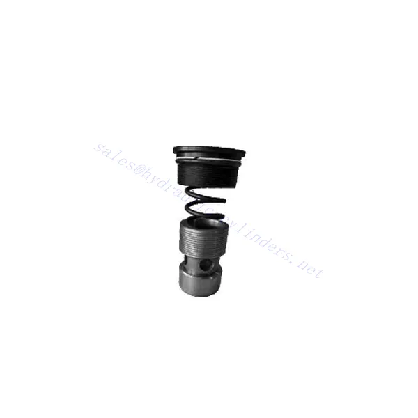
Cartucho de válvula de retención hidráulica serie M-SR
Como cilindros hidráulicos uno de los fabricantes, los surtidores y los exportadores de productos mecánicos, ofrecemos cilindros hidráulicos y muchos otros productos.
Póngase en contacto con nosotros para más información.
Correo:sales@hydraulic-cylinders.net
Fabricante proveedor exportador de cilindros hidráulicos.
Cartucho de válvula de retención hidráulica serie M-SR
El cartucho de válvula de retención hidráulica serie M-SR es versátil y esencial en sistemas hidráulicos. Este cartucho está diseñado para regular el flujo de fluido y evitar el reflujo, ofreciendo un rendimiento confiable, durabilidad y facilidad de instalación.
El cartucho de válvula de retención hidráulica serie M-SR es una solución fiable y eficiente para el control de fluidos en sistemas hidráulicos. Con su eficiente función de válvula de retención, diseño compacto, alta capacidad de caudal y construcción robusta, este cartucho garantiza un rendimiento óptimo del sistema, previene el reflujo y mejora la eficiencia general. Siguiendo las recomendaciones de uso y mantenimiento, el cartucho de válvula de retención hidráulica serie M-SR ofrece un funcionamiento fiable y prolonga la vida útil de los sistemas hidráulicos. Actualice su sistema hidráulico con el cartucho de válvula de retención hidráulica serie m-sr y disfrute de un control de fluidos eficiente y fiable.
Características principales del cartucho de válvula de retención hidráulica serie M-SR:
- Funcionalidad eficiente de la válvula de retención:
- El cartucho de válvula de la serie M-SR cuenta con un mecanismo de válvula de retención incorporado que permite el flujo unidireccional de fluido hidráulico.
- Previene eficazmente el reflujo y garantiza que el fluido fluya en la dirección deseada, minimizando el riesgo de daños e ineficiencia del sistema.
- Diseño compacto y versátil:
- El cartucho de válvula es compacto, lo que lo hace adecuado para aplicaciones con espacio limitado o donde las consideraciones de peso son cruciales.
- Su diseño versátil permite una fácil integración en diversos sistemas hidráulicos, incluida maquinaria móvil, equipos industriales y unidades de energía hidráulica.
- Alta capacidad de flujo:
- A pesar de su tamaño compacto, el cartucho de válvula de la serie M-SR ofrece una alta capacidad de flujo, lo que permite una transferencia de fluido eficiente y un mejor rendimiento del sistema.
- Minimiza las caídas de presión, garantizando una entrega óptima de potencia hidráulica a los actuadores y otros componentes.
- Construcción robusta:
- Construido con materiales de alta calidad, el cartucho de válvula de la serie M-SR demuestra una excelente durabilidad y resistencia al desgaste y la corrosión.
- Está diseñado para soportar condiciones de operación exigentes, prolongando la vida útil del cartucho de la válvula y reduciendo los requisitos de mantenimiento.
Parámetros del cartucho de válvula de retención hidráulica serie M-SR:
| Presupuesto | bar | NG6-30 | |||||
| Presión máxima de funcionamiento | bar | 315 | |||||
| Presión de grietas | bar | Consulte la curva característica | |||||
| Caudal máximo | L/min | Consulte la curva característica | |||||
| Rango de viscosidad | mm2/s | 2,8 a 380 | |||||
| Rango de temperatura del fluido | °C | -30 a +80 (sellos NBR) | |||||
| -20 a +80 (sellos FKM) | |||||||
| Líquido | Aceite mineral apto para juntas NBR y FKM | ||||||
| Éster de fosfato para juntas FKM | |||||||
| Grado de contaminación | Grado máximo permisible de contaminación del fluido: Clase 9. NAS 1638 o 20/18/15, ISO4406 | ||||||
| Tamaño | 8 | 10 | 15 | 20 | 25 | 30 | |
| Peso: Cartucho de válvula de retención en ángulo recto | kilogramo | 0.03 | 0.05 | 0.08 | 0.14 | 0.32 | 0.47 |
Ventajas del cartucho de válvula de retención hidráulica serie M-SR:
NG6-30
• Se utiliza en la instalación de bloques de ruta de aceite.
• Cierre sin fugas
• Varias presiones de apertura disponibles (ver descripción del modelo)
Método de uso del cartucho de válvula de retención hidráulica serie M-SR:
- Análisis del sistema:
- Antes de la instalación, analice exhaustivamente el sistema hidráulico para determinar los requisitos específicos y los parámetros operativos.
- Tenga en cuenta factores como caudales, clasificaciones de presión y compatibilidad con el cartucho de válvula de la serie M-SR.
- Selección de válvulas:
- Seleccione la variante de cartucho de válvula de la serie M-SR adecuada según los requisitos y las especificaciones del sistema.
- Tenga en cuenta factores como la capacidad de flujo, las clasificaciones de presión y la compatibilidad con otros componentes del sistema.
- Instalación:
- Siga las instrucciones del fabricante para instalar correctamente el cartucho de válvula de la serie M-SR en el sistema hidráulico.
- Asegúrese de que haya un ajuste seguro dentro de la cavidad de la válvula, una alineación adecuada con la trayectoria del flujo del fluido y un sellado apropiado para evitar fugas.
- Dirección del flujo del fluido:
- Asegúrese de que el cartucho de válvula de la serie M-SR esté instalado en la orientación correcta, permitiendo la dirección de flujo de fluido deseada.
- Alinee el cartucho de la válvula con la trayectoria de flujo del sistema, asegurando un acoplamiento adecuado del mecanismo de la válvula de retención.
¿Cómo funciona una válvula desviadora hidráulica?
Una válvula desviadora hidráulica es un componente clave en los sistemas hidráulicos que permite al operador redirigir el flujo de fluido hidráulico de una vía a otra. Proporciona flexibilidad para controlar la dirección del flujo y permite el uso de múltiples actuadores hidráulicos con una sola fuente de energía hidráulica. A continuación, se detalla el funcionamiento de una válvula desviadora hidráulica:
- Estructura de la válvula:
- Una válvula desviadora hidráulica generalmente consta de un cuerpo de válvula con múltiples puertos, un carrete o bola móvil y actuadores como palancas, solenoides o mecanismos de presión piloto.
- El cuerpo de la válvula contiene pasajes internos y cámaras que dirigen el flujo del fluido hidráulico.
- Trayectorias de flujo de fluidos:
- La válvula desviadora tiene múltiples puertos que se conectan a diferentes componentes hidráulicos del sistema, como la bomba, el depósito, los actuadores y otras válvulas.
- Estos puertos incluyen un puerto de entrada, puertos de salida y puertos de trabajo, cada uno de los cuales cumple una función específica en el control del flujo del fluido.
- Carrete o bola:
- El cuerpo de la válvula alberga un carrete o bola móvil que controla el flujo de fluido hidráulico.
- El carrete puede deslizarse dentro del cuerpo de la válvula, mientras que la bola puede girar o moverse linealmente para abrir o cerrar pasajes específicos.
- Mecanismos de actuación:
- Las válvulas desviadoras hidráulicas se pueden accionar de forma manual, eléctrica o hidráulica, según el diseño específico y los requisitos de la aplicación.
- El accionamiento manual implica palancas o manijas que el operador mueve físicamente para posicionar el carrete o la bola.
- El accionamiento eléctrico utiliza solenoides que reciben señales eléctricas para mover el carrete o la bola, lo que permite el control remoto y la automatización.
- El accionamiento hidráulico emplea presión piloto para mover el carrete o la bola, a menudo junto con un control eléctrico o manual.
- Posiciones de las válvulas:
- Dependiendo del diseño de la válvula, normalmente hay múltiples posiciones que el carrete o la bola pueden asumir, cada una correspondiente a una ruta de flujo específica.
- Las posiciones comunes incluyen neutral, donde todos los puertos están bloqueados, y varias posiciones de accionamiento que permiten el flujo entre puertos específicos.
- A medida que el carrete o la bola se desplazan, se alinean con puertos específicos, abriendo o cerrando pasajes y dirigiendo el fluido hidráulico en consecuencia.
- Entrada del operador:
- El operador activa la válvula desviadora hidráulica accionando la palanca manual, aplicando señales eléctricas a los solenoides o manipulando la presión piloto.
- Esta entrada determina la posición deseada de la válvula, que a su vez determina la dirección del flujo y la acción de los actuadores hidráulicos.
- Operación del sistema:
- Una vez que la válvula desviadora hidráulica está en la posición deseada, el fluido hidráulico fluye a través de los pasajes y puertos apropiados.
- Este flujo de fluido se puede dirigir a diferentes actuadores hidráulicos, lo que permite un control selectivo del movimiento o funcionamiento del actuador.
Capacidad de la fábrica:
(1) Montaje
Contamos con una plataforma de ensamblaje independiente de primera clase para investigación y desarrollo. El taller de producción de cilindros hidráulicos cuenta con cuatro líneas de ensamblaje de cilindros de elevación semiautomáticos y una línea de ensamblaje de cilindros de inclinación automáticos, con una capacidad de producción anual diseñada de 1 millón de piezas. El taller de cilindros especiales está equipado con un sistema de ensamblaje de limpieza semiautomático de diversas especificaciones, con una capacidad de producción anual diseñada de 200,000 unidades, y está equipado con reconocidos equipos de mecanizado CNC, un centro de mecanizado, equipos especiales de procesamiento de cilindros de alta precisión, una máquina de soldadura robotizada, una máquina de limpieza automática, una máquina de ensamblaje de cilindros automáticos y una línea de producción de pintura automática. Contamos con más de 300 equipos críticos. La asignación óptima y el uso eficiente de los recursos de equipo garantizan la precisión y la alta calidad de los productos.


(2) Mecanizado
El taller de mecanizado está equipado con un centro de torneado de carril inclinado personalizado, un centro de mecanizado, una máquina de bruñido de alta velocidad, un robot de soldadura y otros equipos relacionados, que pueden procesar tubos cilíndricos con un diámetro interior máximo de 400 mm y una longitud máxima de 6 metros.

(3) Soldadura

(4) Pintura y revestimiento
Con pequeñas y medianas líneas de cilindros automáticos de recubrimiento de pintura a base de agua, para lograr la carga y descarga automática de robots y pulverización automática, la capacidad de diseño de 4000 piezas por turno;
También disponemos de una línea semiautomática de producción de pintura para grandes cilindros accionada por cadena, con una capacidad de diseño de 60 cajas por turno.


(5) Pruebas
Disponemos de instalaciones de inspección y bancos de pruebas de primera clase para garantizar que el rendimiento del cilindro cumple los requisitos.

Somos uno de los mejores fabricantes de cilindros hidráulicos. Ofrecemos cilindros hidráulicos integrales. También proporcionamos... cajas de cambios agrícolasHemos exportado nuestros productos a clientes de todo el mundo y nos hemos ganado una excelente reputación gracias a nuestra excelente calidad y servicio posventa. Invitamos a clientes nacionales e internacionales a contactarnos para negociar negocios, intercambiar información y... colabore con nosotros!
Cilindro hidráulico Aplicación:
