
WMR Series Directional Hydraulic Valve With Mechanical, Manual Operation
Como cilindros hidráulicos uno de los fabricantes, los surtidores y los exportadores de productos mecánicos, ofrecemos cilindros hidráulicos y muchos otros productos.
Póngase en contacto con nosotros para más información.
Correo:sales@hydraulic-cylinders.net
Fabricante proveedor exportador de cilindros hidráulicos.
WMR Series Directional Hydraulic Valve With Mechanical, Manual Operation
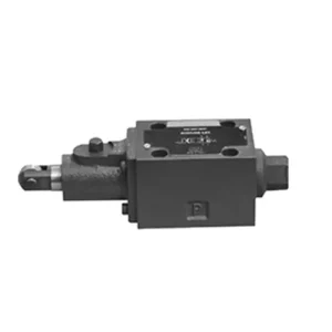
The WMR series directional hydraulic valve with mechanical, manual operation is a cutting-edge solution designed to deliver precise control in hydraulic systems. This valve offers enhanced efficiency and flexibility with its advanced features and robust construction.
The WMR series directional hydraulic valve with mechanical, manual operation is a reliable and versatile solution for hydraulic systems. Its automatic and manual operation and precise directional control offer enhanced flexibility and control for various applications. Following the recommended usage methods and adhering to regular maintenance practices, the WMR series valve will continue providing efficient and reliable operation. Upgrade your hydraulic system with the WMR series directional hydraulic valve and experience the benefits of enhanced control and versatility.
WMR Series Directional Hydraulic Valve With Mechanical, Manual Operation Key Characteristics:
- Funcionamiento mecánico y manual:
- The WMR series valve features a mechanical, manual operation, allowing operators to control the valve position manually.
- Esto proporciona flexibilidad y control en aplicaciones donde se desea o se requiere la operación manual.
- Control direccional:
- This hydraulic valve enables precise directional fluid flow control within the hydraulic system.
- Permite a los operadores seleccionar la ruta de flujo deseada, garantizando un funcionamiento eficiente y fiable.
- Construcción duradera:
- The WMR series valve is constructed with high-quality materials, ensuring durability and longevity.
- Its robust design can withstand demanding operating conditions, providing reliable performance.
- Amplia gama de aplicaciones:
- The WMR series valve suits various industries and applications, including manufacturing, construction, agriculture, etc.
- It can be utilized in hydraulic systems that require accurate and efficient fluid control.
WMR Series Directional Hydraulic Valve With Mechanical, Manual Operation Parameter:
NG6
| Posición de instalación | Opcional | ||
| Rango de temperatura del fluido | °C | -30 a +80 (sellos NBR) | |
| -20 a +80 (sellos FKM) | |||
| Presión máxima de funcionamiento del puerto | Puerto ABP | bar | 315 |
| Puerto T | bar | 60 | |
| Caudal máximo | L/min | 60 | |
| Sección transversal del flujo (posición neutra conmutada) | Tipo Q | mm2 | For symbol Q, 6% of the nominal cross-section |
| Tipo W | mm2 | For symbol W, 3% of the nominal cross-section | |
| Líquido | Aceite mineral; Éster de fosfato | ||
| Rango de viscosidad | mm2/s | 2,8 a 500 | |
| Grado de contaminación | Grado máximo permisible de contaminación del fluido: Clase 9. NAS 1638 o 20/18/15, ISO4406 | ||
| Peso | kilogramo | 1.4 | |
NG10
| Posición de instalación | Opcional | ||
| Rango de temperatura del fluido | °C | -30 a +80 (sellos NBR) | |
| -20 a +80 (sellos FKM) | |||
| Presión máxima de funcionamiento del puerto | Puerto ABP | bar | 315 |
| Puerto T | bar | 60 | |
| Caudal máximo | L/min | 120 | |
| Sección transversal del flujo (posición neutra conmutada) | Tipo V | mm2 | 11(A/B → T);10.3(P → A/B) |
| Tipo W | mm2 | 2.5(A/B → T) | |
| Tipo Q | mm2 | 5.5(A/B → T) | |
| Líquido | Aceite mineral; Éster de fosfato | ||
| Rango de viscosidad | mm2/s | 2,8 a 500 | |
| Grado de contaminación | Grado máximo permisible de contaminación del fluido: Clase 9. NAS 1638 o 20/18/15, ISO4406 | ||
| Peso | kilogramo | 4 | |
WMR Series Directional Hydraulic Valve With Mechanical, Manual Operation Advantages:
• Válvula corredera direccional de acción directa
• Scroll wheel can rotate 90°
• Nineteen standard slide valve functions
Usage Method Of WMR Series Directional Hydraulic Valve With Mechanical, Manual Operation:
- Integración de sistemas:
- Identify the appropriate location for the WMR series valve within the hydraulic system, considering the desired flow direction and control requirements.
- Asegúrese de la compatibilidad con las especificaciones de presión y flujo del sistema.
- Monte la válvula de forma segura utilizando los soportes o accesorios de montaje adecuados.
- Conexiones de fluidos:
- Seleccione accesorios y mangueras hidráulicas compatibles para conexiones seguras y sin fugas.
- Siga las instrucciones del fabricante para conocer los valores de torsión adecuados durante el proceso de instalación.
- Utilice selladores de roscas o cinta adhesiva adecuados para garantizar un sellado fiable.
- Funcionamiento manual:
- Familiarícese con el mecanismo de accionamiento manual de la válvula, incluyendo la palanca o el mando utilizado para controlar su posición.
- Ensure the operator understands the correct procedure for manually adjusting the valve position.
- Calibración del sistema:
- Calibre la posición y el movimiento de la válvula de acuerdo con la dirección de flujo deseada y los requisitos de control.
- Ajuste la válvula manualmente para lograr el flujo deseado y asegurar su correcto funcionamiento.
How To Adjust Hydraulic Valve Lifters?
Adjusting hydraulic valve lifters is a crucial maintenance task to ensure proper engine performance and prevent issues like valve train noise and reduced power. Here’s a step-by-step guide on how to adjust hydraulic valve lifters:
- Prepare the Engine:
- Before starting the adjustment process, make sure the engine is turned off and cool to the touch.
- Remove any components necessary to access the valve covers, such as the air cleaner assembly or spark plug wires.
- Identify the Correct Valve Adjustment Sequence:
- Consult the engine manufacturer’s specifications or service manual to determine the correct valve adjustment sequence for your specific engine.
- Some engines have a firing order that dictates the sequence, while others have specific instructions based on cylinder numbering.
- Locate the Top Dead Center (TDC) Position:
- Rotate the engine’s crankshaft in the normal direction of rotation until the number one piston reaches the top dead center (TDC) position on its compression stroke.
- Use a timing mark on the harmonic balancer or flywheel and a timing pointer to determine the TDC position accurately.
- Adjusting Valve Lifters:
- Start with the first cylinder in the valve adjustment sequence.
- Remove the valve cover to access the rocker arms and valve lifters.
- Loosen the lock nut on the rocker’s arm using an appropriate wrench or socket.
- Turn the adjusting screw or stud on the rocker’s arm clockwise to decrease the valve clearance or counterclockwise to increase it.
- Check the engine manufacturer’s specifications for the recommended valve clearance. Use a feeler gauge to measure the clearance between the rocker arm and the valve stem.
- Adjust the valve lifter until the proper clearance is achieved. You should feel slight resistance but still be able to move the feeler gauge back and forth.
- Hold the adjusting screw or stud in place and tighten the lock nut securely.
- Repita el proceso:
- Move to the next cylinder in the valve adjustment sequence and repeat steps 4 and 5 until all the valve lifters have been adjusted.
- Reinstall Valve Covers:
- Once you’ve completed the valve adjustment on all cylinders, reinstall the valve covers and ensure they are properly sealed to prevent oil leaks.
- Double-Check:
- After adjusting the valve lifters, it’s advisable to go through the entire valve adjustment sequence once more to confirm that all clearances are within the specified range.
Capacidad de la fábrica:
(1) Montaje
Contamos con una plataforma de ensamblaje independiente de primera clase para investigación y desarrollo. El taller de producción de cilindros hidráulicos cuenta con cuatro líneas de ensamblaje de cilindros de elevación semiautomáticos y una línea de ensamblaje de cilindros de inclinación automáticos, con una capacidad de producción anual diseñada de 1 millón de piezas. El taller de cilindros especiales está equipado con un sistema de ensamblaje de limpieza semiautomático de diversas especificaciones, con una capacidad de producción anual diseñada de 200,000 unidades, y está equipado con reconocidos equipos de mecanizado CNC, un centro de mecanizado, equipos especiales de procesamiento de cilindros de alta precisión, una máquina de soldadura robotizada, una máquina de limpieza automática, una máquina de ensamblaje de cilindros automáticos y una línea de producción de pintura automática. Contamos con más de 300 equipos críticos. La asignación óptima y el uso eficiente de los recursos de equipo garantizan la precisión y la alta calidad de los productos.


(2) Mecanizado
El taller de mecanizado está equipado con un centro de torneado de carril inclinado personalizado, un centro de mecanizado, una máquina de bruñido de alta velocidad, un robot de soldadura y otros equipos relacionados, que pueden procesar tubos cilíndricos con un diámetro interior máximo de 400 mm y una longitud máxima de 6 metros.

(3) Soldadura

(4) Pintura y revestimiento
Con pequeñas y medianas líneas de cilindros automáticos de recubrimiento de pintura a base de agua, para lograr la carga y descarga automática de robots y pulverización automática, la capacidad de diseño de 4000 piezas por turno;
También disponemos de una línea semiautomática de producción de pintura para grandes cilindros accionada por cadena, con una capacidad de diseño de 60 cajas por turno.


(5) Pruebas
Disponemos de instalaciones de inspección y bancos de pruebas de primera clase para garantizar que el rendimiento del cilindro cumple los requisitos.

Somos uno de los mejores fabricantes de cilindros hidráulicos. Ofrecemos cilindros hidráulicos integrales. También proporcionamos... cajas de cambios agrícolasHemos exportado nuestros productos a clientes de todo el mundo y nos hemos ganado una excelente reputación gracias a nuestra excelente calidad y servicio posventa. Invitamos a clientes nacionales e internacionales a contactarnos para negociar negocios, intercambiar información y... colabore con nosotros!
Cilindro hidráulico Aplicación:
