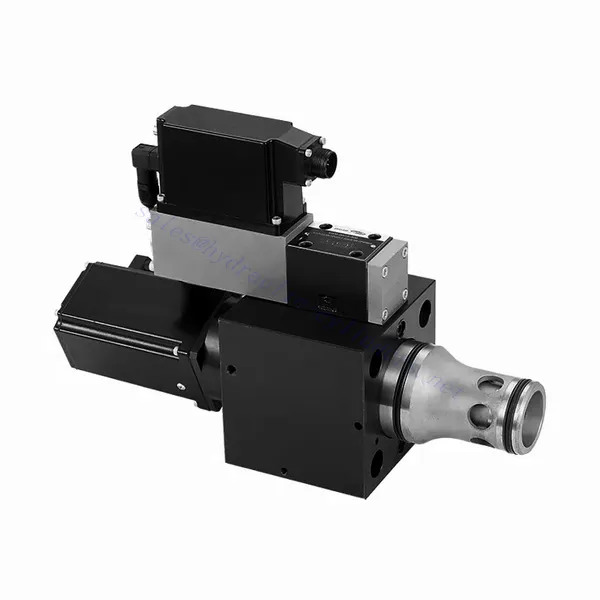
Válvula hidráulica de flujo de alta respuesta de 2 y 3 vías serie WRCE
Como cilindros hidráulicos uno de los fabricantes, los surtidores y los exportadores de productos mecánicos, ofrecemos cilindros hidráulicos y muchos otros productos.
Póngase en contacto con nosotros para más información.
Correo:sales@hydraulic-cylinders.net
Fabricante proveedor exportador de cilindros hidráulicos.
Válvula hidráulica de flujo de alta respuesta de 2 y 3 vías serie WRCE
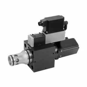
The WRCE series 2- and 3-way high-response flow hydraulic valve is a remarkable hydraulic component designed to deliver exceptional performance in fluid control applications. With its high-response flow capabilities, this valve revolutionizes hydraulic systems by providing precise and efficient flow control.
The WRCE series 2- and 3-way high-response flow hydraulic valve sets new standards in flow control precision and efficiency. With its high-response flow capabilities, compact design, and versatility, this valve empowers hydraulic systems to achieve optimal performance and energy efficiency. By following the recommended usage methods and maintenance guidelines, you can harness the full potential of the WRCE series valve and experience enhanced control and productivity in your hydraulic applications. Upgrade your hydraulic system today and unlock the advantages of efficiency and precision with the WRCE series 2- and 3-way high-response flow hydraulic valve.
WRCE Series 2-and 3-way High-response Flow Hydraulic Valve Key Characteristics:
- High-Response Flow:
- The WRCE series valve is engineered to offer high-response flow control, ensuring rapid and accurate adjustments to fluid flow rates.
- This characteristic enables precise control over hydraulic actuators, resulting in enhanced system performance, reduced energy consumption, and improved overall efficiency.
- Versatile 2- and 3-Way Configuration:
- This valve is available in both 2-way and 3-way configurations, providing flexibility to meet various hydraulic system requirements.
- The 2-way configuration allows for simple on/off control, while the 3-way design enables directional control, making it ideal for applications such as actuator extension and retraction.
- Diseño compacto:
- The WRCE series valve features a compact design, making it suitable for installations where space is limited.
- This compact size allows easy integration into various hydraulic systems without compromising performance or functionality.
- High-Pressure Rating:
- This valve is built to withstand high-pressure environments, ensuring reliable operation even in demanding hydraulic applications.
- Its robust construction and high-pressure rating make it suitable for use in systems that require efficient flow control under extreme operating conditions.
WRCE Series 2-and 3-way High-response Flow Hydraulic Valve Parameter:
| General | |||||
| NS NG | 32 | 40 | 50 | ||
| Peso | kilogramo | 11.2 | 17.3 | 24.6 | |
| Weight with shut-off valve …../…WK or …/…WL… | kilogramo | 12.5 | 18.6 | 25.9 | |
| Size of the pilot control valve (pilot) | NG | 6 | 6 | 6 | |
| Posición de instalación | Any, preferably horizontal | ||||
| Rango de temperatura de almacenamiento | °C | –20 to +80 | |||
| Circunstancias rango de temperatura | °C | –20 to +50 | |||
| Hydraulic (measured with HLP32, ϑoil=40℃ ±5℃) | |||||
| Presión máxima de funcionamiento | – Main stagePort A、B | bar | NS 32~40: 350,NS 50: 420 | ||
| – Pilot control valve port X | 315 | ||||
| – Pilot control valve port Y | 210 | ||||
| Rated flow Δp=5bar | – Specifications …S…L (linear) | L/min | 800 | 1200 | 2000 |
| – Specifications …S…R (linear with progressive fine control range) | 600 | 850 | 1400 | ||
| Nominal flow of pilot valve at Δp=70bar | L/min | 12 | 40 | 40 | |
| Leakage of pilot valve at P=100bar | L/min | 0.3 | 0.7 | 0.7 | |
| Fluido hidráulico | Mineral oil (HL,HLP) to DIN 51524 | ||||
| Rango de temperatura del fluido hidráulico | °C | 20 to +80;preferably +40 to +50 | |||
| Rango de viscosidad | mm2/s | 20 to 380;preferably 30 to 45 | |||
| Maximum admissible degree of contamination of the hydraulic fluid, cleanliness class according to ISO 4406 (c) | Class 20/18/15 | ||||
| Histéresis | % | ≤ 0.2 | |||
| Histéresis | % | ≤ 0.1 | |||
| Sensibilidad de respuesta | % | ≤ 0.1 | |||
| Response Time(step signa 0 ~ 100%) | EM | ≤ 20 | |||
| Datos eléctricos | |||||
| Tipo de voltaje | Direct voltage | ||||
| Type of signal | Analog | ||||
| Opening point calibration | % | ≦ 1 | |||
| Zero shift upon change of: | – Hydraulic fluid temperature | %/10K | ≦ 0.3 | ≦ 0.3 | ≦ 0.3 |
| – Pilot pressure in X | %/100bar | ≦ 0.7 | ≦ 0.7 | ≦ 0.7 | |
| – Return flow pressure in Y | %/bar | ≦ 0.3 | ≦ 0.3 | ≦ 0.3 | |
| The protection class of the valve according to EN60529 | IP65 with a mating connector mounted and locked | ||||
WRCE Series 2-and 3-way High-response Flow Hydraulic Valve Advantages:
• Pilot-operated two-stage cartridge high-frequency response throttle valve
• Suitable for closed-loop control of position, pressure, force and speed
• Pilot control valve: six-port direct-acting high-frequency response proportional valve with electric feedback
• Main stage: closed loop position control
• Integrated open loop and closed loop control electronics (OBE)
Usage Method Of WRCE Series 2-and 3-way High-response Flow Hydraulic Valve :
- Evaluación del sistema:
- Evaluate your hydraulic system and determine the specific flow control requirements.
- Identify whether the WRCE series valve is compatible with your system based on factors such as flow rates, pressure ratings, and the desired control functions.
- Selección de válvulas:
- Select the appropriate variant of the WRCE series valve based on your system parameters and flow control needs.
- Consider factors such as flow capacity, pressure rating, response time, and compatibility with your specific application.
- Instalación:
- Follow the manufacturer’s installation instructions carefully to ensure proper alignment and secure mounting of the valve.
- Make sure to create leak-free connections by using suitable hydraulic fittings, adapters, and seals. Tighten the connections adequately to prevent any fluid leaks.
- Integración de señales de control:
- Connect the control signal lines of the valve to a suitable control device, such as a hydraulic control module, electronic control unit, or manual control lever.
- Ensure proper wiring and compatibility between the valve and control device to achieve accurate and responsive flow control.
How To Hook Up Hydraulic Control Valve?
To hook up a hydraulic control valve, follow these steps:
- Identificar el tipo de válvula: Determine the specific type of hydraulic control valve you are working with, such as a directional control valve, pressure control valve, or flow control valve. Ensure that the valve is suitable for your application and compatible with your hydraulic system.
- Reúna las herramientas y los materiales necesarios: Collect the necessary tools and materials, including appropriate hydraulic fittings, adapters, hoses, and wrenches. Refer to the manufacturer’s instructions for any specific tools or components needed.
- Prepare el sistema hidráulico: Apague el sistema hidráulico y libere la presión activando la válvula de alivio o retrayendo los cilindros hidráulicos. Este paso es crucial para la seguridad y evita movimientos accidentales o fugas de fluido hidráulico.
- Identificar la dirección del flujo: Determine la dirección del flujo en su sistema hidráulico. Normalmente, la dirección del flujo se indica mediante flechas en los componentes hidráulicos. Asegúrese de comprender la dirección correcta del flujo antes de continuar.
- Localizar el punto de instalación: Identify the optimal location to install the hydraulic control valve in your hydraulic system. Consider factors such as accessibility, proximity to the actuator or hydraulic component, and ease of operation. Ensure there is enough space for the valve to be mounted securely.
- Monte la válvula: Securely mount the hydraulic control valve in the chosen location using appropriate brackets or clamps. Ensure the valve is positioned correctly, aligning the inlet and outlet ports with the flow direction. Follow the manufacturer’s instructions for the specific mounting requirements of your valve.
- Conecte los puertos de entrada y salida: Attach hydraulic hoses or tubing to the inlet and outlet ports of the hydraulic control valve. Use suitable hydraulic fittings and adapters to create a leak-free connection. Tighten the connections using wrenches to ensure a secure fit, but avoid over-tightening.
- Connect Control Lines: If your hydraulic control valve requires external control signals, connect the control lines from the control device, such as a joystick, lever, or solenoid, to the appropriate ports on the valve. Follow the manufacturer’s instructions for the correct wiring or connection configuration.
- Pruebe el sistema: Once the hydraulic control valve is installed, slowly restore hydraulic system pressure. Test the system to ensure that the valve is functioning correctly. Operate the control device and observe the response of the hydraulic components to verify that the valve is controlling the flow, pressure, or direction as intended.
- Fine-tune and Adjust: Make any necessary adjustments to the hydraulic control valve to achieve the desired flow, pressure, or direction control. Refer to the manufacturer’s instructions for specific adjustment procedures. Regularly monitor the system for any leaks, pressure inconsistencies, or abnormal behavior.
Capacidad de la fábrica:
(1) Montaje
Contamos con una plataforma de ensamblaje independiente de primera clase para investigación y desarrollo. El taller de producción de cilindros hidráulicos cuenta con cuatro líneas de ensamblaje de cilindros de elevación semiautomáticos y una línea de ensamblaje de cilindros de inclinación automáticos, con una capacidad de producción anual diseñada de 1 millón de piezas. El taller de cilindros especiales está equipado con un sistema de ensamblaje de limpieza semiautomático de diversas especificaciones, con una capacidad de producción anual diseñada de 200,000 unidades, y está equipado con reconocidos equipos de mecanizado CNC, un centro de mecanizado, equipos especiales de procesamiento de cilindros de alta precisión, una máquina de soldadura robotizada, una máquina de limpieza automática, una máquina de ensamblaje de cilindros automáticos y una línea de producción de pintura automática. Contamos con más de 300 equipos críticos. La asignación óptima y el uso eficiente de los recursos de equipo garantizan la precisión y la alta calidad de los productos.


(2) Mecanizado
El taller de mecanizado está equipado con un centro de torneado de carril inclinado personalizado, un centro de mecanizado, una máquina de bruñido de alta velocidad, un robot de soldadura y otros equipos relacionados, que pueden procesar tubos cilíndricos con un diámetro interior máximo de 400 mm y una longitud máxima de 6 metros.

(3) Soldadura

(4) Pintura y revestimiento
Con pequeñas y medianas líneas de cilindros automáticos de recubrimiento de pintura a base de agua, para lograr la carga y descarga automática de robots y pulverización automática, la capacidad de diseño de 4000 piezas por turno;
También disponemos de una línea semiautomática de producción de pintura para grandes cilindros accionada por cadena, con una capacidad de diseño de 60 cajas por turno.


(5) Pruebas
Disponemos de instalaciones de inspección y bancos de pruebas de primera clase para garantizar que el rendimiento del cilindro cumple los requisitos.

Somos uno de los mejores fabricantes de cilindros hidráulicos. Ofrecemos cilindros hidráulicos integrales. También proporcionamos... cajas de cambios agrícolasHemos exportado nuestros productos a clientes de todo el mundo y nos hemos ganado una excelente reputación gracias a nuestra excelente calidad y servicio posventa. Invitamos a clientes nacionales e internacionales a contactarnos para negociar negocios, intercambiar información y... colabore con nosotros!
Cilindro hidráulico Aplicación:
