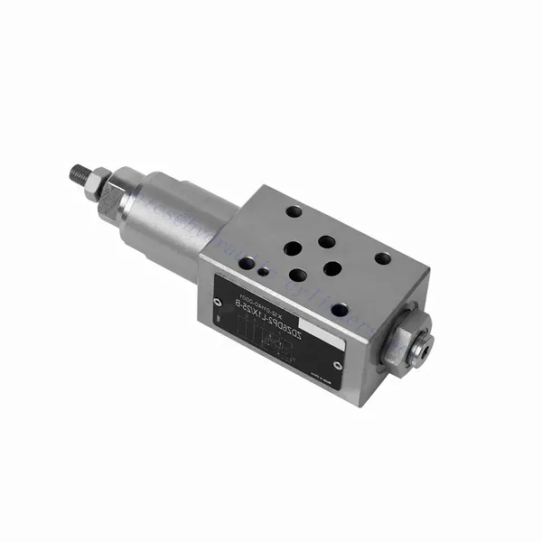
Válvula hidráulica de secuencia de presión de accionamiento directo serie ZDZ
Como cilindros hidráulicos uno de los fabricantes, los surtidores y los exportadores de productos mecánicos, ofrecemos cilindros hidráulicos y muchos otros productos.
Póngase en contacto con nosotros para más información.
Correo:sales@hydraulic-cylinders.net
Fabricante proveedor exportador de cilindros hidráulicos.
Válvula hidráulica de secuencia de presión de accionamiento directo serie ZDZ
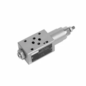
La válvula hidráulica de secuencia de presión de operación directa serie ZDZ es un producto de vanguardia que proporciona un control y secuenciación de presión precisos en sistemas hidráulicos. Gracias a su avanzado diseño de operación directa y su excepcional funcionalidad, esta válvula garantiza un control preciso de la secuencia de presiones hidráulicas, lo que permite un funcionamiento eficiente de diversos circuitos hidráulicos.
La válvula hidráulica de secuencia de presión de operación directa serie ZDZ es una solución confiable para el control preciso de la presión y la secuenciación en sistemas hidráulicos. Gracias a su diseño de operación directa, regulación precisa de la presión, operación secuencial y amplio rango de presión, esta válvula garantiza el funcionamiento eficiente y coordinado de múltiples circuitos hidráulicos. Siguiendo las recomendaciones de uso y mantenimiento, la válvula de la serie ZDZ ofrece un rendimiento constante, prolongando la vida útil de los sistemas hidráulicos. Actualice su sistema hidráulico con la válvula hidráulica de secuencia de presión de operación directa serie ZDZ y disfrute de un control de presión y una secuenciación óptimos para una mayor eficiencia y productividad del sistema.
Características principales de la válvula hidráulica de secuencia de presión de operación directa serie ZDZ:
- Diseño de operación directa:
- La válvula de la serie ZDZ presenta un diseño de operación directa, eliminando la necesidad de circuitos piloto externos.
- Este diseño simplifica la instalación, reduce la complejidad del sistema y mejora la eficiencia general.
- Control de presión preciso:
- Esta válvula ofrece una precisión excepcional en el control de presión, garantizando una regulación de presión precisa y confiable en sistemas hidráulicos.
- Permite un ajuste preciso y el mantenimiento de los niveles de presión deseados, mejorando el rendimiento del sistema.
- Operación secuencial:
- La válvula de la serie ZDZ permite el funcionamiento secuencial de circuitos hidráulicos, controlando el orden en que ocurren los diferentes procesos.
- Esta característica garantiza un funcionamiento fluido y coordinado, optimizando la eficiencia y la productividad del sistema.
- Amplio rango de presión:
- La válvula está disponible en varios rangos de presión, lo que la hace adecuada para diversos sistemas y aplicaciones hidráulicas.
- Esta versatilidad permite la personalización para satisfacer requisitos específicos de control de presión, adaptándose a diversas necesidades operativas.
Parámetros de la válvula hidráulica de secuencia de presión de operación directa serie ZDZ:
| Presupuesto | NG6 | NG10 | |||
| Líquido | Aceite mineral apto para juntas NBR y FKM | ||||
| Éster de fosfato para juntas FKM | |||||
| Rango de temperatura del fluido | °C | -30 ~ +80 (sellos NBR) | |||
| -20 ~ +80 (sellos FKM) | |||||
| Rango de viscosidad | mm2/s | 10 ~ 800 | |||
| Grado de contaminación | Grado máximo permisible de contaminación del fluido: Clase 9. NAS 1638 o 20/18/15, ISO4406 | ||||
| Presión máxima de funcionamiento | Puerto A, B, X | bar | 315 | 210 | |
| Puerto Y | bar | 160 | |||
| Presión máxima de secuencia establecida | bar | 25; 75; 150; 210; 315 | / | ||
| Presión de secuencia máxima establecida (ajustable) Puerto B | bar | / | 25; 75; 150; 210; | ||
| Caudal máximo | L/min | 60 | 80 | ||
| Peso | kilogramo | alrededor de 1.6 | alrededor de 3 | ||
Ventajas de la válvula hidráulica de secuencia de presión de operación directa serie ZDZ:
NG6
• Estructura directa
• La cara de instalación sigue las normas DIN 24340 A e ISO 4401
• Cinco rangos de presión
• Dos tipos de ajuste: perilla, tornillo de ajuste con tapa de protección
• Con interfaz de manómetro
• Válvula unidireccional opcional
NG10
• Estructura directa
• La cara de instalación sigue las normas DIN 24340 A e ISO 4401
• Cuatro rangos de presión
• Dos tipos de ajuste: perilla, tornillo de ajuste con tapa de protección
• Con interfaz de manómetro
• Válvula unidireccional opcional
Método de uso de la válvula hidráulica de secuencia de presión de operación directa serie ZDZ:
- Análisis del sistema:
- Realice un análisis integral del sistema hidráulico para determinar los requisitos específicos de control de presión y secuenciación.
- Tenga en cuenta los niveles de presión deseados, los diferenciales de presión y los caudales en diferentes circuitos.
- Selección de válvulas:
- Seleccione la variante de válvula de la serie ZDZ adecuada según las especificaciones de control de presión y secuenciación.
- Tenga en cuenta la clasificación de presión, la capacidad de flujo y la compatibilidad con otros componentes del sistema.
- Instalación:
- Siga las instrucciones del fabricante para instalar correctamente la válvula de secuencia de presión de operación directa de la serie ZDZ del sistema hidráulico.
- Asegúrese de que la alineación sea adecuada y de que las conexiones sean seguras para evitar fugas y optimizar el rendimiento.
- Calibración:
- Calibre la válvula para establecer los niveles de presión y la secuencia deseados.
- Utilice manómetros u otros dispositivos de medición para ajustar la válvula para un control de presión óptimo y preciso.
¿Cómo funciona una servoválvula hidráulica?
Una servoválvula hidráulica es una válvula de control de precisión que se utiliza en sistemas hidráulicos para regular con precisión el flujo y la dirección del fluido hidráulico. Funciona convirtiendo una señal eléctrica en una salida hidráulica, lo que permite un control y posicionamiento precisos de los actuadores hidráulicos. Así es como funciona una servoválvula hidráulica:
- Construcción de la válvula:
- Una servoválvula hidráulica consta de un cuerpo de válvula, un mecanismo de carrete o asiento y conexiones eléctricas.
- El cuerpo de la válvula contiene puertos de entrada y salida para el fluido hidráulico, mientras que el carrete o asiento controla el flujo de fluido a través de la válvula.
- Entrada eléctrica:
- Se envía una señal de entrada eléctrica, generalmente de un sistema de control o un dispositivo de retroalimentación, a la servoválvula.
- Esta señal eléctrica representa la posición o nivel de control deseado para el actuador hidráulico.
- Etapa piloto:
- La señal de entrada eléctrica es recibida por la etapa piloto de la servoválvula.
- La etapa piloto generalmente consta de una pequeña válvula solenoide o un motor de torsión que recibe y convierte la señal eléctrica en una fuerza mecánica.
- Movimiento del carrete o del asiento:
- La fuerza mecánica generada por la etapa piloto mueve el carrete o asiento dentro del cuerpo de la válvula.
- El movimiento del carrete o del asiento controla el tamaño y la posición de los conductos de flujo, regulando así el flujo del fluido hidráulico.
- Salida hidráulica:
- A medida que el carrete o el asiento se mueven, permiten que el fluido hidráulico fluya a través de la válvula, dirigiéndolo al actuador hidráulico apropiado.
- El flujo de fluido hacia el actuador hace que éste se mueva, logrando la posición o el control deseado según lo determinado por la señal de entrada eléctrica.
- Sistema de retroalimentación:
- En algunos sistemas de servoválvulas, se emplea un mecanismo de retroalimentación para proporcionar información sobre la posición o el estado real del actuador.
- Esta retroalimentación se utiliza para comparar con la posición deseada, lo que permite un ajuste continuo y un control preciso.
- Bucle de control:
- La servoválvula funciona en un sistema de control de circuito cerrado, donde la información de retroalimentación se compara continuamente con la señal de entrada deseada.
- Cualquier desviación entre la posición real y la deseada se corrige ajustando la posición del carrete o del asiento de la servoválvula.
- Ejemplos de aplicación:
- Las servoválvulas hidráulicas se utilizan comúnmente en aplicaciones que requieren un control preciso, como robótica, sistemas aeroespaciales, maquinaria industrial y simuladores de vuelo.
Capacidad de la fábrica:
(1) Montaje
Contamos con una plataforma de ensamblaje independiente de primera clase para investigación y desarrollo. El taller de producción de cilindros hidráulicos cuenta con cuatro líneas de ensamblaje de cilindros de elevación semiautomáticos y una línea de ensamblaje de cilindros de inclinación automáticos, con una capacidad de producción anual diseñada de 1 millón de piezas. El taller de cilindros especiales está equipado con un sistema de ensamblaje de limpieza semiautomático de diversas especificaciones, con una capacidad de producción anual diseñada de 200,000 unidades, y está equipado con reconocidos equipos de mecanizado CNC, un centro de mecanizado, equipos especiales de procesamiento de cilindros de alta precisión, una máquina de soldadura robotizada, una máquina de limpieza automática, una máquina de ensamblaje de cilindros automáticos y una línea de producción de pintura automática. Contamos con más de 300 equipos críticos. La asignación óptima y el uso eficiente de los recursos de equipo garantizan la precisión y la alta calidad de los productos.


(2) Mecanizado
El taller de mecanizado está equipado con un centro de torneado de carril inclinado personalizado, un centro de mecanizado, una máquina de bruñido de alta velocidad, un robot de soldadura y otros equipos relacionados, que pueden procesar tubos cilíndricos con un diámetro interior máximo de 400 mm y una longitud máxima de 6 metros.

(3) Soldadura

(4) Pintura y revestimiento
Con pequeñas y medianas líneas de cilindros automáticos de recubrimiento de pintura a base de agua, para lograr la carga y descarga automática de robots y pulverización automática, la capacidad de diseño de 4000 piezas por turno;
También disponemos de una línea semiautomática de producción de pintura para grandes cilindros accionada por cadena, con una capacidad de diseño de 60 cajas por turno.


(5) Pruebas
Disponemos de instalaciones de inspección y bancos de pruebas de primera clase para garantizar que el rendimiento del cilindro cumple los requisitos.

Somos uno de los mejores fabricantes de cilindros hidráulicos. Ofrecemos cilindros hidráulicos integrales. También proporcionamos... cajas de cambios agrícolasHemos exportado nuestros productos a clientes de todo el mundo y nos hemos ganado una excelente reputación gracias a nuestra excelente calidad y servicio posventa. Invitamos a clientes nacionales e internacionales a contactarnos para negociar negocios, intercambiar información y... colabore con nosotros!
Cilindro hidráulico Aplicación:
