ZDR-seeria otsejuhitav rõhu alandav hüdrauliline ventiil
ZDR-seeria otsejuhitav rõhu alandav hüdrauliline ventiil
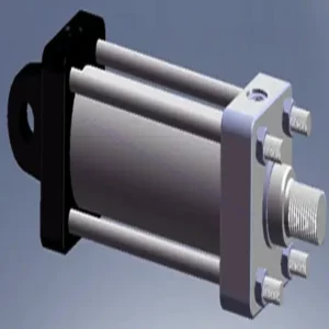
The ZDR series direct-operated pressure-reducing hydraulic valve is a highly efficient and reliable component that provides accurate pressure control in hydraulic systems. With its direct-operated design and exceptional performance, this valve ensures precise pressure reduction to meet specific system requirements.
The ZDR series direct-operated pressure-reducing hydraulic valve is a high-performance solution for precise pressure control in hydraulic systems. With its direct-operated design, accurate pressure control, wide pressure range, and high flow capacity, this valve ensures efficient and reliable pressure reduction while protecting system components. By following the recommended usage methods and maintenance practices, the ZDR series valve delivers reliable performance, extending the lifespan of hydraulic systems. Upgrade your hydraulic system with the ZDR series direct-operated pressure-reducing hydraulic valve and experience optimal pressure control for enhanced system efficiency and productivity.
ZDR Series Direct Operated Pressure Reducing Hydraulic Valve Key Characteristics:
- Otsejuhtimisega disain:
- The ZDR series valve features a direct-operated design, which enables it to provide precise pressure control without the need for external pilot circuits.
- This design simplifies installation and reduces complexity in hydraulic systems.
- Täpne rõhu reguleerimine:
- This valve offers exceptional accuracy in pressure control, allowing hydraulic systems to maintain the desired pressure range with high reliability.
- It ensures stable operation and protects sensitive system components from excessive pressure.
- Lai rõhuvahemik:
- The ZDR series valve is available in various pressure ranges, making it suitable for diverse hydraulic applications.
- The flexibility in pressure range allows customization to match specific system requirements and optimize performance.
- Suur läbilaskevõime:
- This valve exhibits excellent flow capacity, enabling it to handle high flow rates while maintaining precise pressure control.
- It ensures efficient fluid regulation and uninterrupted system operation, even in demanding applications.
ZDR Series Direct Operated Pressure Reducing Hydraulic Valve Parameter:
| Spetsifikatsioonid | NG10 | NG16 | ||
| Vedelik | NBR- ja FKM-tihenditele sobiv mineraalõli | |||
| Fosfaatestrid FKM-tihendi jaoks | ||||
| Vedeliku temperatuurivahemik | ℃ | -30 to +80 (NBR seals) | ||
| -20 kuni +80 (FKM tihendid) | ||||
| Viskoossusvahemik | mm2/s | 10 kuni 800 | ||
| Saastumise aste | Vedeliku maksimaalne lubatud saastumisaste: klass 9. NAS 1638 või 20/18/15, ISO4406 | |||
| Nominal pressure | baar | 315 | ||
| Maksimaalne töörõhk | Port P | baar | 315 | |
| Maksimaalne töörõhk | Port A | baar | 315 | 250 |
| Maksimaalne töörõhk | Y-sadam | baar | Separate and at zero pressure to tank | |
| Rõhu seadistamine | Min. | baar | Dependent on the flow (see curves) | |
| Max. | baar | 50; 100; 200; 315 | 50; 100; 200; 250 | |
| Maksimaalne voolukiirus | L/min | 120 | 220 | |
| Kaal | kg | umbes 6,5 | about 8.8 | |
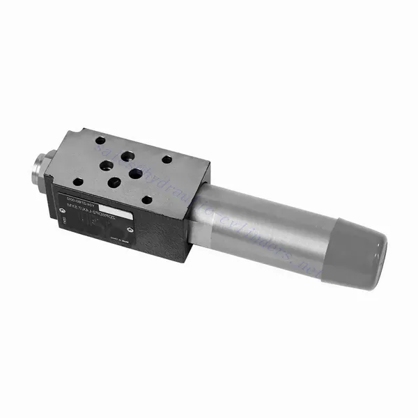
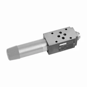
ZDR Series Direct Operated Pressure Reducing Hydraulic Valve Advantages:
• Sandwich-tüüpi struktuur
• Paigalduspind vastab standarditele DIN 24340 A ja ISO 4401
• Neli rõhuvahemikku
• Kaks reguleerimistüüpi: nupp, kaitsekorgiga reguleerimiskruvi
• Manomeetri liidesega
• Valikuline ühesuunaline ventiil
Usage Method Of ZDR Series Direct Operated Pressure Reducing Hydraulic Valve:
- Süsteemianalüüs:
- Conduct a thorough hydraulic system analysis to determine the specific pressure control requirements.
- Consider maximum operating pressure, desired pressure range, and flow rates.
- Ventiili valik:
- Select the appropriate ZDR series valve variant based on the system’s pressure control specifications.
- Arvestage rõhuklassiga, voolumahuga ja ühilduvusega teiste süsteemi komponentidega.
- Paigaldamine:
- Follow the manufacturer’s instructions to correctly install the ZDR series direct-operated pressure-reducing valve in the hydraulic system.
- Lekete vältimiseks ja jõudluse optimeerimiseks veenduge õiges joonduses ja kindlates ühendustes.
- Kalibreerimine:
- Calibrate the valve to set the desired downstream pressure.
- Kasutage ventiili optimaalse rõhukontrolli täpseks reguleerimiseks manomeetreid või muid mõõteseadmeid.
How Does A Hydraulic Selector Valve Work?
A hydraulic selector valve, also known as a hydraulic diverter valve or hydraulic control valve, is a device used to direct the flow of hydraulic fluid in a hydraulic system. It allows the operator to control the path of fluid flow by selecting different hydraulic circuits or components to operate. Here’s a breakdown of how a hydraulic selector valve works:
- Ventiili konstruktsioon:
- A hydraulic selector valve consists of a body with multiple ports and internal passages.
- It typically has an actuating mechanism, such as a lever or a solenoid, to control the movement of the valve spool or poppet.
- Port Configuration:
- A selector valve has multiple ports, usually labeled as A, B, and C, or sometimes referred to as P, T, and A/B/C.
- Port P (Pressure) connects to the hydraulic pump or the high-pressure side of the system.
- Port T (Tank) connects to the hydraulic reservoir or the low-pressure side of the system.
- Ports A, B, and C are the output ports that connect to different hydraulic circuits or components.
- Ventiili asendid:
- The selector valve has different positions that determine the flow path of the hydraulic fluid.
- Common positions include “A,” “B,” “C,” “AB,” “AC,” and “BC,” depending on the specific valve design.
- Vedelikuvoolu kontroll:
- When the valve is in the neutral or default position, typically labeled “N,” the fluid flow is blocked, and no flow occurs between any of the ports.
- When the operator actuates the valve by moving the lever or energizing the solenoid, the valve spool or poppet shifts to a different position, enabling fluid flow.
- Flow Path Selection:
- By moving the actuating mechanism, the operator can select the desired flow path.
- For example, when the valve is in position “A,” fluid flows from port P to port A, allowing the hydraulic circuit or component connected to port A to operate.
- Multiple Flow Paths:
- Depending on the specific valve design, a hydraulic selector valve can provide multiple flow paths.
- For instance, in position “AB,” fluid can flow from port P to both ports A and B simultaneously, allowing operation of two separate hydraulic circuits or components.
- Juhtimine ja kasutamine:
- The actuating mechanism of the selector valve can be manual, where the operator physically moves a lever or knob, or it can be electric or pneumatic, using solenoids or other control devices.
- Electrically controlled selector valves can be integrated into automated systems or controlled remotely.
- System Flexibility:
- Hydraulic selector valves provide flexibility in system design and operation.
- They allow the operator to switch between different hydraulic circuits or components, facilitating tasks such as equipment positioning, attachment control, or switching between different implements.
Tehase võimekus ja suutlikkus:
(1) Kokkupanek
Meil on esmaklassiline sõltumatu teadus- ja arendustegevuse montaažiplatvorm. Hüdrosilindrite tootmistöökojas on neli poolautomaatset tõstesilindrite koosteliini ja üks automaatne kallutussilindrite koosteliin, mille kavandatud aastane tootmisvõimsus on 1 miljon tükki. Spetsiaalsete silindrite töökoda on varustatud erinevate spetsifikatsioonidega poolautomaatse puhastusmontaažisüsteemiga, mille kavandatud aastane tootmisvõimsus on 200 000 ja mis on varustatud kuulsate CNC-töötlemisseadmete, mehaanilise töötlemise keskuse, suure täpsusega silindrite töötlemise eriseadmete, robotkeevitusmasina, automaatse puhastusmasina, automaatse silindri kokkupanemise masina ja automaatse värvimise tootmisliiniga. Olemasolevad kriitilised seadmed rohkem kui 300 komplekti (komplekti). Seadmete ressursside optimaalne jaotamine ja tõhus kasutamine tagavad toodete täpsusnõuded ja vastavad toodete kvaliteedinõuetele.


(2) Töötlemine
Töödeldav töökoda on varustatud kohandatud kallutatud rööpse treipingi keskuse, mehaanilise keskuse, kiire lihvimismasina, keevitusroboti ja muude seotud seadmetega, mis suudavad töödelda silindritorusid, mille maksimaalne siseläbimõõt on 400 mm ja maksimaalne pikkus on 6 meetrit.

(3) Keevitamine

(4) Värvimine ja katmine
Väikese ja keskmise suurusega silindri automaatse veepõhise värvipinnakattega liinide abil, et saavutada automaatne robotlaadimine ja mahalaadimine ning automaatne pihustamine, projekteerimisvõimsus 4000 tükki vahetuse kohta;
Meil on ka poolautomaatne suurte balloonide värvimise tootmisliin, mis töötab jõukettaga ja mille projekteerimisvõimsus on 60 kasti ühe vahetuse kohta.


(5) Testimine
Meil on esmaklassilised kontrolliseadmed ja katsestendid, et tagada silindri jõudlus vastavus nõuetele.

Oleme üks parimaid hüdrosilindrite tootjaid. Pakume laia valikut hüdrosilindreid. Pakume ka vastavaid... põllumajanduslikud käigukastid. Oleme eksportinud oma tooteid klientidele üle maailma ja teeninud hea maine tänu meie suurepärasele tootekvaliteedile ja müügijärgsele teenindusele. Me tervitame kliente kodus ja välismaal, et võtta meiega ühendust, et pidada läbirääkimisi äri, vahetada teavet ja teha meiega koostööd!