30SD10-40 solenoidne suunaventiil
30SD10-40 solenoidne suunaventiil
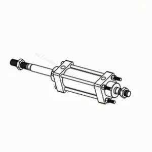
30SD10-40 solenoid-suunaventiil on suure jõudlusega tööstuskomponent, mis on loodud täpse ja usaldusväärse vedeliku juhtimise tagamiseks mitmesugustes rakendustes. Oma täiustatud funktsioonide, vastupidava konstruktsiooni ja kasutajasõbraliku disainiga pakub see solenoid-suunaventiil suuremat efektiivsust ja töökindlust.
30SD10-40 solenoid-suunaventiil on usaldusväärne ja mitmekülgne komponent, mis pakub täpset vedeliku juhtimist tööstuslikes rakendustes. Selle vastupidav konstruktsioon, täpne juhtimine ja usaldusväärne jõudlus suurendavad vedeliku juhtimissüsteemide efektiivsust ja tootlikkust. Soovitatavate kasutusmeetodite ja hooldusjuhiste järgimisega saate tagada 30SD10-40 solenoid-suunaventiili optimaalse jõudluse ja pikaealisuse oma tööstustegevuses.
30SD10-40 solenoid-suunaventiili omadused:
- Vastupidav konstruktsioon: 30SD10-40 solenoid-suunaventiil on valmistatud erakordse meisterlikkuse ja kvaliteetsete materjalidega, tagades vastupidavuse ja pikaealisuse. Selle vastupidav konstruktsioon võimaldab sellel vastu pidada nõudlikele tööstuskeskkondadele, pakkudes usaldusväärset jõudlust isegi karmides tingimustes.
- Mitmekülgne funktsionaalsus: See solenoid-suunaventiil pakub mitmekülgset funktsionaalsust, mistõttu sobib see laias valikus rakendusteks. See kontrollib tõhusalt vedeliku voolu suunda, võimaldades täpset ja tõhusat tööd erinevates tööstussüsteemides.
- Täppisjuhtimine: 30SD10-40 solenoid-suunaventiil pakub vedeliku juhtimisel erakordset täpsust. See võimaldab vedeliku suuna ja rõhu täpset reguleerimist ja seadistamist, tagades optimaalse jõudluse ja efektiivsuse tööstusprotsessides.
- Usaldusväärne jõudlus: See solenoid-suunaventiil tagab usaldusväärse jõudluse, minimeerides süsteemi rikete või katkestuste ohtu. See töötab usaldusväärselt, aidates kaasa tootlikkuse suurenemisele ja seisakute vähendamisele tööstustegevuses.
30SD10-40 solenoid-suunaventiili parameeter:
| Nimirõhk | 207 baari (3000 psi) | |
| Tippvool | 23 l/min (6 gallonit minutis) | |
| Vedelik | Mineraal- või sünteetilised õlid määrdeomadustega | |
| Temperatuurivahemik ℃ | -54 kuni 107 ℃ (polüuretaanist tihendid) | |
| -40 kuni 100 ℃ (Buna N tihendid) | ||
| -26 kuni 204 ℃ (fluorosüsiniktihendid) | ||
| Viskoossusvahemik | 7,4 kuni 420 mm2/s | |
| Saastumise aste | Minimaalne saastetase on ISO4406 tase 20/18/14 ja kasutusea pikendamiseks on soovitatav tase 17/15/13. | |
| Sisemine leke | ≤ 82 ml/min 207 baari juures | |
| Õõnsus | VC10-4 | |
| Mähise töömaht | Pidev nimipinge vahemikus 85% kuni 115% | |
| Esialgne mähise voolutugevus 20 ℃ juures | E-mähis | 1,7 A 12 V alalisvoolu korral; 0,85 A 24 V alalisvoolu korral |
| D-mähis | 1,67 A 12 V alalisvoolu juures; 0,83 A 24 V alalisvoolu juures | |
| Minimaalne sissetõmbepinge | 85% nimiväärtusest 207 baari juures | |
30SD10-40 solenoid-suunaventiili eelised:
• Pideva töörežiimiga mähis
• Padrunid on pinge järgi vahetatavad
• Valikulised veekindlad E-mähised kuni IP69K kaitseklassiga
• Tõhus märgarmatuuri konstruktsioon
• Tööstusharu ühine õõnsus
• Karastatud osad pika eluea tagamiseks
30SD10-40 solenoid-suunaventiili kasutusmeetod :
- Integration into the System: Integrate the 30SD10-40 Solenoid Directional Valve into the fluid control system following the manufacturer’s guidelines and specifications. Ensure proper alignment and connection between the valve and other system components to achieve optimal performance.
- Elektriühendus: Looge solenoid-suunaventiilile turvaline elektriühendus. Järgige kaasasolevat ühendusskeemi ja veenduge õiges polaarsuses, et vältida elektrilisi rikkeid. Elektriühendustega töötamisel järgige ohutusjuhiseid.
- Vedeliku voolu suuna juhtimine: vedeliku voolu suuna juhtimiseks kasutage solenoid-suunaventiili. Ventiil on tavaliselt varustatud käsitsi reguleerimiseks mõeldud hoova või ajamiga. Teise võimalusena saab selle integreerida automatiseeritud juhtimissüsteemi kaugjuhtimiseks.
- Pressure Adjustment: Use the solenoid directional valve to regulate fluid pressure within the system. Adjust the valve’s settings to achieve the desired pressure levels for optimal performance and efficiency.
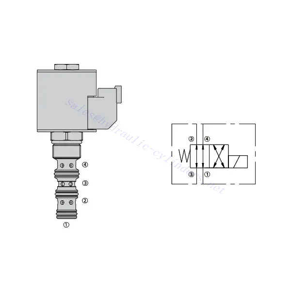
Kuidas lugeda hüdraulilise klapi skeeme?
Hüdrauliliste ventiilide skeemide lugemine nõuab hüdrauliliste sümbolite ja nende tähenduste põhiteadmisi. Siin on sammud, mis aitavad teil hüdrauliliste ventiilide skeeme lugeda:
- Tutvuge hüdrauliliste sümbolitega: Hüdraulilistes skeemides kasutatakse erinevate komponentide ja funktsioonide kujutamiseks graafilisi sümboleid. Levinud sümbolite hulka kuuluvad ruudud ventiilide, jooned torude või voolikute, nooled voolu suuna ja ringid rõhu- või vooluhulga reguleerimisseadmete jaoks. Enne jätkamist veenduge, et saate nende sümbolite tähendusest aru.
- Tuvastage ventiilide tüübid: Otsige skeemilt ventiilide sümboleid. Ventiile saab kujutada erineva kuju ja suunaga ruutudena. Näiteks diagonaaljoonega ruut tähistab tagasilöögiklappi, samas kui noolega ruut tähistab suunaventiili.
- Määrake ventiili funktsioon: Iga klapi sümbol näitab selle konkreetset funktsiooni. Suunaventiilid määravad hüdraulikavedeliku voolusuuna, rõhuventiilid aga reguleerivad rõhutasemeid. Vooluventiilid juhivad vedeliku voolukiirust ja tagasilöögiventiilid võimaldavad voolu ainult ühes suunas.
- Jälgige ventiili ühendusi: Pöörake tähelepanu klapi sümbolisse sisenevatele ja sealt väljuvatele joontele või nooltele. Need jooned tähistavad hüdraulilise vedeliku vooluteid. Nooled näitavad voolu suunda ja klappe ning teisi komponente ühendavad jooned näitavad ühendusi.
- Analüüsige ventiilide asendeid: Mõned hüdraulilise klapi skeemid sisaldavad sümboleid, mis illustreerivad klapi positsioone. Need sümbolid kujutavad tavaliselt klapi pooli või kangi erinevates asendites, näiteks avatud, suletud või osaliselt avatud. Klapi asendite mõistmine aitab teil määrata vooluteid ja hüdraulikasüsteemi olekut.
- Kaaluge täiendavaid sümboleid ja märkusi: Hüdraulilised skeemid võivad sisaldada täiendavaid sümboleid ja märkusi, mis tähistavad manomeetreid, voolumõõtureid, filtreid, akumulaatoreid või muid komponente. Tutvuge nende sümbolite ja nende tähendustega, et saada süsteemist terviklik arusaam.
- Järgige vooluteid: Jälgige vooluteid hüdraulilisest jõuallikast läbi erinevate ventiilide ja komponentide ajami või soovitud väljundini. Saage aru, kuidas ventiilid üksteisega suhtlevad ja kuidas nad kontrollivad vedeliku voolu, rõhku ja suunda soovitud süsteemi toimimise saavutamiseks.
- Vaadake legendi või võtit: Skeemil peaks olema legend või legend, mis selgitab iga diagrammil kasutatud sümboli tähendust. Kui kohtate tundmatuid sümboleid või teil on nende tähenduses kahtlusi, vaadake selgituste saamiseks legendi.
- Vajadusel otsige lisaressursse: Kui vajate hüdrauliliste ventiilide skeemide põhjalikumat mõistmist, kaaluge hüdraulikaõpikute, veebiressursside või hüdraulikaekspertidega konsulteerimist, kes saavad pakkuda teie konkreetsetele vajadustele vastavaid juhiseid ja selgitusi.
Tehase võimekus ja suutlikkus:
(1) Kokkupanek
Meil on esmaklassiline sõltumatu teadus- ja arendustegevuse montaažiplatvorm. Hüdrosilindrite tootmistöökojas on neli poolautomaatset tõstesilindrite koosteliini ja üks automaatne kallutussilindrite koosteliin, mille kavandatud aastane tootmisvõimsus on 1 miljon tükki. Spetsiaalsete silindrite töökoda on varustatud erinevate spetsifikatsioonidega poolautomaatse puhastusmontaažisüsteemiga, mille kavandatud aastane tootmisvõimsus on 200 000 ja mis on varustatud kuulsate CNC-töötlemisseadmete, mehaanilise töötlemise keskuse, suure täpsusega silindrite töötlemise eriseadmete, robotkeevitusmasina, automaatse puhastusmasina, automaatse silindri kokkupanemise masina ja automaatse värvimise tootmisliiniga. Olemasolevad kriitilised seadmed rohkem kui 300 komplekti (komplekti). Seadmete ressursside optimaalne jaotamine ja tõhus kasutamine tagavad toodete täpsusnõuded ja vastavad toodete kvaliteedinõuetele.


(2) Töötlemine
Töödeldav töökoda on varustatud kohandatud kallutatud rööpse treipingi keskuse, mehaanilise keskuse, kiire lihvimismasina, keevitusroboti ja muude seotud seadmetega, mis suudavad töödelda silindritorusid, mille maksimaalne siseläbimõõt on 400 mm ja maksimaalne pikkus on 6 meetrit.

(3) Keevitamine

(4) Värvimine ja katmine
Väikese ja keskmise suurusega silindri automaatse veepõhise värvipinnakattega liinide abil, et saavutada automaatne robotlaadimine ja mahalaadimine ning automaatne pihustamine, projekteerimisvõimsus 4000 tükki vahetuse kohta;
Meil on ka poolautomaatne suurte balloonide värvimise tootmisliin, mis töötab jõukettaga ja mille projekteerimisvõimsus on 60 kasti ühe vahetuse kohta.


(5) Testimine
Meil on esmaklassilised kontrolliseadmed ja katsestendid, et tagada silindri jõudlus vastavus nõuetele.

Oleme üks parimaid hüdrosilindrite tootjaid. Pakume laia valikut hüdrosilindreid. Pakume ka vastavaid... põllumajanduslikud käigukastid. Oleme eksportinud oma tooteid klientidele üle maailma ja teeninud hea maine tänu meie suurepärasele tootekvaliteedile ja müügijärgsele teenindusele. Me tervitame kliente kodus ja välismaal, et võtta meiega ühendust, et pidada läbirääkimisi äri, vahetada teavet ja teha meiega koostööd!