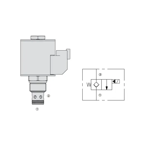
35SD10-20 solenoidne suunaventiil
Üheks hüdrosilindrite tootjaks, tarnijaks ja mehaaniliste toodete eksportijaks pakume hüdrosilindreid ja paljusid teisi tooteid.
Palun võtke meiega ühendust üksikasjade saamiseks.
Post:sales@hydraulic-cylinders.net
Tootja tarnija eksportija hüdrosilindrid.
35SD10-20 solenoidne suunaventiil
The 35SD10-20 Solenoid Directional Valve is a powerful and versatile component designed to optimize fluid control in a wide range of industrial applications. With its advanced features, precise operation, and reliable performance, this solenoid valve is a valuable tool for enhancing fluid control efficiency and productivity. Whether in manufacturing, automation, or process control, the 35SD10-20 Solenoid Directional Valve delivers exceptional functionality and versatility, making it an essential component for modern industries.
The 30SD08-47D Solenoid Directional Valve is a reliable and versatile component that optimizes fluid control in various industrial applications. With its robust construction, precise fluid control, versatility, and space-efficient design, this solenoid valve offers exceptional performance, ensuring efficient and reliable operations. By incorporating the 30SD08-47D Solenoid Directional Valve into fluid control systems, industries can achieve enhanced productivity, accuracy, and system performance. Invest in this advanced solenoid valve to optimize your industrial processes, streamline operations, and achieve success in your industry.
35SD10-20 Solenoid Directional Valve Characteristics:
- Robust Construction: The 35SD10-20 Solenoid Directional Valve is built with a robust and durable design, ensuring long-lasting performance even in demanding environments. Its sturdy construction allows it to withstand high pressures, temperature fluctuations, and harsh conditions, providing consistent and reliable operation.
- Precise Fluid Control: This solenoid valve offers precise control over fluid flow, enabling accurate and efficient regulation of liquids or gases. With its responsive solenoid mechanism, the valve allows for fast and reliable switching between different flow paths, ensuring precise control and minimizing flow disruptions.
- Versatile Functionality: The 35SD10-20 Solenoid Directional Valve is designed to accommodate various applications in different industries. It can be used for direction control, on/off switching, and pressure regulation, providing flexibility and adaptability in fluid control systems.
- Efficient Energy Consumption: This solenoid valve is designed with energy efficiency in mind. It minimizes power consumption during operation, resulting in cost savings and environmental benefits. The valve’s efficient energy usage makes it a sustainable choice for businesses looking to optimize their resource utilization.
35SD10-20 Solenoid Directional Valve Parameter:
| Nimirõhk | 241 bar (3500 psi) | |
| Tippvool | 56.8 L/min (15 gpm) ; See performance chart | |
| Vedelik | Mineraal- või sünteetilised õlid määrdeomadustega | |
| Vedeliku temperatuurivahemik ℃ | -54 kuni 107 ℃ (polüuretaanist tihendid) | |
| -40 kuni 100 ℃ (Buna N tihendid) | ||
| -26 kuni 204 ℃ (fluorosüsiniktihendid) | ||
| Viskoossusvahemik | 7,4 kuni 420 mm2/s | |
| Saastumise aste | Minimaalne saastetase on ISO4406 tase 18/16/13 ja kasutusea pikendamiseks on soovitatav tase 15/13/11. | |
| Sisemine leke | ≤ 0.15 mL/min (3 drops /min) @241 bar | |
| Õõnsus | VC10-2 | |
| Mähise töömaht | Pidev nimipinge vahemikus 85% kuni 115% | |
| Esialgne mähise voolutugevus 20 ℃ juures | E-mähis | 1,7 A 12 V alalisvoolu korral; 0,85 A 24 V alalisvoolu korral |
| D-mähis | 1,67 A 12 V alalisvoolu juures; 0,83 A 24 V alalisvoolu juures | |
| Minimaalne sissetõmbepinge | 85% of nominal at 241 bar | |
35SD10-20 Solenoid Directional Valve Advantages:
• Pideva töörežiimiga mähis
• Tõhus märgarmatuuri konstruktsioon
• Padrunid on pinge järgi vahetatavad
• Valikulised veekindlad E-mähised kuni IP69K kaitseklassiga
• Tööstusharu ühine õõnsus
• Karastatud osad pika eluea ja vähese lekke tagamiseks
Usage Method Of 35SD10-20 Solenoid Directional Valve:
Paigaldamine:
- Follow the manufacturer’s instructions for proper installation of the 35SD10-20 Solenoid Directional Valve.
- Ensure correct alignment and connection to the fluid control system, using appropriate fittings and seals for leak-free operation.
Elektriühendused:
- Connect the solenoid valve to the power supply, following the specified voltage and electrical requirements.
- Ensure proper wiring and insulation to ensure safe and reliable electrical operation.
Fluid Flow Direction:
- Determine the desired fluid flow direction based on your application requirements.
- The 35SD10-20 Solenoid Directional Valve provides various ports and positions for inlet, outlet, and exhaust. Consult the product documentation for correct port connections.
Control Signal:
- Connect the control signal, whether electrical or pneumatic, to the solenoid valve to activate its switching mechanism.
- Ensure that the control signal is compatible with the valve’s specifications and operating parameters.
Kuidas ühendada hüdraulilise voolu reguleerimisventiili?
Hüdraulilise voolu juhtventiili ühendamiseks toimige järgmiselt.
- Tuvastage ventiili tüüp: Määrake kindlaks, millist tüüpi voolukontrollventiili te kasutate. Levinud tüüpide hulka kuuluvad nõelventiilid, reguleeritavad voolukontrollventiilid või rõhukompensatsiooniga voolukontrollventiilid. Veenduge, et ventiil sobib teie rakenduse jaoks ja ühildub teie hüdraulikasüsteemiga.
- Koguge vajalikud tööriistad ja materjalid: Koguge kokku vajalikud tööriistad ja materjalid, sh sobivad hüdraulilised liitmikud, adapterid, voolikud ja mutrivõtmed.
- Hüdraulikasüsteemi ettevalmistamine: Lülitage hüdrosüsteem välja ja vabastage süsteemis olev rõhk, aktiveerides ülerõhuventiili või tõmmates sisse kõik hüdrosilindrid. See samm on ohutuse tagamiseks ülioluline.
- Voolu suuna määramine: Tehke kindlaks voolu suund oma hüdraulikasüsteemis. Tavaliselt on voolu suund näidatud hüdraulikakomponentidel olevate nooltega. Enne jätkamist veenduge, et saate aru õigest voolu suunast.
- Paigalduspunkti leidmine: Määrake oma hüdraulikasüsteemis voolu reguleerimisventiili paigaldamiseks optimaalne asukoht. Arvestage selliste teguritega nagu ligipääsetavus, ajami või hüdraulikakomponendi lähedus ja reguleerimise lihtsus.
- Paigaldage ventiil: Paigaldage voolu reguleerimisventiil valitud kohta kindlalt sobivate kronsteinide või klambrite abil. Veenduge, et ventiil on õigesti paigutatud, joondades sisse- ja väljalaskeava voolusuunaga.
- Ühendage sisse- ja väljalaskeportid: Kinnitage hüdraulikavoolikud või -torud voolu reguleerimisventiili sisse- ja väljalaskeavade külge. Lekkevaba ühenduse loomiseks kasutage sobivaid hüdraulikaliitmikke ja adaptereid. Pingutage ühendusi mutrivõtmete abil, et tagada kindel kinnitus, kuid ärge pingutage üle.
- Voolu juhtimise reguleerimine: Depending on the type of flow control valve, it may have adjustable features such as a needle valve or a flow control knob. Adjust the valve according to your desired flow rate or speed. Refer to the manufacturer’s instructions for specific adjustment procedures.
- Testige süsteemi: Kui voolu reguleerimisventiil on paigaldatud ja reguleeritud, taastage aeglaselt hüdraulikasüsteemi rõhk. Testige süsteemi, et veenduda voolu reguleerimisventiili korrektses toimimises. Jälgige hüdraulilise ajami voolukiirust või kiirust, et veenduda, et see on soovitud vahemikus.
- Häälestamine ja jälgimine: Reguleerige voolu reguleerimisventiili soovitud voolukiiruse või kiiruse saavutamiseks. Jälgige regulaarselt hüdraulikasüsteemi lekete, rõhu ebajärjekindluse või ebatavalise käitumise suhtes.
Tehase võimekus ja suutlikkus:
(1) Kokkupanek
Meil on esmaklassiline sõltumatu teadus- ja arendustegevuse montaažiplatvorm. Hüdrosilindrite tootmistöökojas on neli poolautomaatset tõstesilindrite koosteliini ja üks automaatne kallutussilindrite koosteliin, mille kavandatud aastane tootmisvõimsus on 1 miljon tükki. Spetsiaalsete silindrite töökoda on varustatud erinevate spetsifikatsioonidega poolautomaatse puhastusmontaažisüsteemiga, mille kavandatud aastane tootmisvõimsus on 200 000 ja mis on varustatud kuulsate CNC-töötlemisseadmete, mehaanilise töötlemise keskuse, suure täpsusega silindrite töötlemise eriseadmete, robotkeevitusmasina, automaatse puhastusmasina, automaatse silindri kokkupanemise masina ja automaatse värvimise tootmisliiniga. Olemasolevad kriitilised seadmed rohkem kui 300 komplekti (komplekti). Seadmete ressursside optimaalne jaotamine ja tõhus kasutamine tagavad toodete täpsusnõuded ja vastavad toodete kvaliteedinõuetele.


(2) Töötlemine
Töödeldav töökoda on varustatud kohandatud kallutatud rööpse treipingi keskuse, mehaanilise keskuse, kiire lihvimismasina, keevitusroboti ja muude seotud seadmetega, mis suudavad töödelda silindritorusid, mille maksimaalne siseläbimõõt on 400 mm ja maksimaalne pikkus on 6 meetrit.

(3) Keevitamine

(4) Värvimine ja katmine
Väikese ja keskmise suurusega silindri automaatse veepõhise värvipinnakattega liinide abil, et saavutada automaatne robotlaadimine ja mahalaadimine ning automaatne pihustamine, projekteerimisvõimsus 4000 tükki vahetuse kohta;
Meil on ka poolautomaatne suurte balloonide värvimise tootmisliin, mis töötab jõukettaga ja mille projekteerimisvõimsus on 60 kasti ühe vahetuse kohta.


(5) Testimine
Meil on esmaklassilised kontrolliseadmed ja katsestendid, et tagada silindri jõudlus vastavus nõuetele.

Oleme üks parimaid hüdrosilindrite tootjaid. Pakume laia valikut hüdrosilindreid. Pakume ka vastavaid... põllumajanduslikud käigukastid. Oleme eksportinud oma tooteid klientidele üle maailma ja teeninud hea maine tänu meie suurepärasele tootekvaliteedile ja müügijärgsele teenindusele. Me tervitame kliente kodus ja välismaal, et võtta meiega ühendust, et pidada läbirääkimisi äri, vahetada teavet ja teha meiega koostööd!
Hüdrosilindri kasutamine:
