
4WRA(E) seeria otsejuhitav proportsionaalne hüdrauliline suunaventiil
Üheks hüdrosilindrite tootjaks, tarnijaks ja mehaaniliste toodete eksportijaks pakume hüdrosilindreid ja paljusid teisi tooteid.
Palun võtke meiega ühendust üksikasjade saamiseks.
Post:sales@hydraulic-cylinders.net
Tootja tarnija eksportija hüdrosilindrid.
4WRA(E) seeria otsejuhitav proportsionaalne hüdrauliline suunaventiil
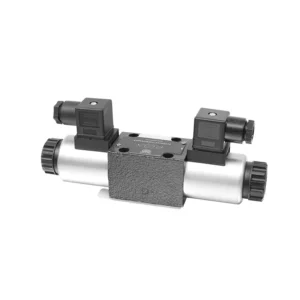
4WRA(E) seeria otsejuhtimisega proportsionaalne hüdrauliline suunaventiil on tipptasemel hüdrauliline komponent, mis on loodud hüdraulikasüsteemide täpse juhtimise ja tõhusa töö tagamiseks. Oma otsejuhtimisega proportsionaalse suunajuhtimistehnoloogiaga pakub see ventiil täpset vooluhulga juhtimist, sujuvaid suunamuutusi ja optimeeritud jõudlust.
4WRA(E) seeria otsejuhtimisega proportsionaalne hüdrauliline suunaventiil annab hüdraulikasüsteemidele täpse vooluhulga juhtimise, mitmekülgsed suunamuutused ja optimaalse energiatõhususe. Selle otsejuhtimisega proportsionaalne juhtimistehnoloogia tagab täpse ja reageeriva töö, samas kui suur vooluhulk ja energiasäästlik disain aitavad kaasa süsteemi paremale jõudlusele. Soovitatavate kasutusmeetodite ja hooldusjuhiste järgimisega saate maksimeerida 4WRA(E) seeria ventiili eeliseid ja pikaealisust, viies oma hüdraulikasüsteemi uuele täpsuse ja efektiivsuse tasemele. Uuendage oma hüdraulikasüsteemi juba täna ja kogege 4WRA(E) seeria otsejuhtimisega proportsionaalse suunaventiili võimsust.
4WRA(E) seeria otsejuhitava proportsionaalse suunalise hüdraulilise ventiili peamised omadused:
- Otsene proportsionaalne juhtimine:
- 4WRA(E) seeria ventiil kasutab otsejuhitavat proportsionaalset juhtimist, mis võimaldab täpset ja kohest reageerimist juhtsignaalidele.
- See funktsioon tagab täpse vooluhulga juhtimise ja sujuva ülemineku erinevate hüdrauliliste funktsioonide vahel.
- Suur läbilaskevõime:
- Oma vastupidava konstruktsiooniga pakub ventiil suurt vooluvõimsust, mistõttu sobib see rakenduste jaoks, mis nõuavad märkimisväärset hüdraulilist võimsust.
- See võimaldab tõhusalt käsitseda suuri vedelikumahte, aidates kaasa süsteemi jõudluse paranemisele.
- Mitmekülgne suunakontroll:
- 4WRA(E) seeria ventiil pakub mitmekülgset suuna juhtimist, võimaldades hüdraulikavedeliku suuna sujuvat ja täpset muutmist.
- See võimaldab hüdrauliliste komponentide, näiteks silindrite, mootorite ja ajamite sujuvat aktiveerimist eri suundades.
- Energiatõhusus:
- See energiatõhusust silmas pidades konstrueeritud ventiil minimeerib rõhulanguseid ja optimeerib vooluhulga juhtimist, mille tulemuseks on väiksem energiatarbimine.
- Hüdraulilise võimsuse tõhusa haldamise abil aitab see maksimeerida süsteemi jõudlust ja minimeerida tegevuskulusid.
4WRA(E) seeria otsejuhitav proportsionaalne suunaline hüdrauliline ventiil Parameeter:
| Hüdrauliline | ||||||||
| Paigaldusasend | valikuline, eelistatavalt horisontaalne | |||||||
| Suurus | 6 | 10 | ||||||
| Kaal | 4WRA…L2X | Kg | 2 | 6.6 | ||||
| 4WRAE…L2X | 2.2 | 6.8 | ||||||
| Nimivoolukiirus qnom, kui Δp = 10 baari | L/min | 7, 15, 26 | 30, 60 | |||||
| Hüsterees | % | ≤5 | ||||||
| Korduvus | % | ≤1 | ||||||
| Vastuse tundlikkus | % | ≤0,5 | ||||||
| Maksimaalne töörõhk | Sadama loomsete kõrvalsaaduste büroo | baar | 315 | |||||
| Sadam T | baar | 210 | ||||||
| Vedelik | NBR- ja FKM-tihenditele sobiv mineraalõli | |||||||
| Fosfaatestrid FKM-tihendi jaoks | ||||||||
| Vedeliku temperatuurivahemik | 4WRA…L2X | ℃ | -20 ℃ kuni 70 ℃ (-4 °F kuni 158 °F) | |||||
| 4WRAE…L2X | ℃ | -20 ℃ kuni 50 ℃ (-4 °F kuni 122 °F) | ||||||
| Viskoossusvahemik | mm²/s | 20 kuni 380 (eelistatavalt 30 kuni 46) | ||||||
| Saastumise aste | NAS1638 klass 9 või ISO 4406 klass 20/18/15 | |||||||
| Elektrilised andmed | ||||||||
| 1) solenoid | ||||||||
| Pinge tüüp | DC | |||||||
| Käskluse väärtuse signaal | ±10 V või 4–20 mA | |||||||
| Maksimaalne voolutugevus solenoidi kohta | A | 2.5 | 1.5 | 0.8 | ||||
| Mähise takistus | Külmväärtus | Ω | 2 | 4.8 | 19.5 | |||
| Maksimaalne soojusväärtus | 3 | 7.2 | 28.8 | |||||
| Kohustus | % | ED100% | ||||||
| Mähise temperatuur | ℃ | 150 | ||||||
| Ventiilikaitse vastavalt standardile EN 60529 | IP65 | |||||||
| 2) Juhtelektroonika | ||||||||
| Võimendi | 4WRA…L2X | VT-VSPA2-L2X | ||||||
| 4WRAE…L2X | Ventiili integreeritud (OBE) | |||||||
| Tööpinge | Nimipinge | V alalisvool | 24 | |||||
| Alumine piirväärtus | V | 21/22(4WRA), 19(4WRAE) | ||||||
| Ülemine piirväärtus | V | 35 | ||||||
| Võimendi voolutarve | Imax | A | <1,8 | |||||
| Imax | A | 3 | ||||||
4WRA(E) seeria otsejuhitava proportsionaalse suunalise hüdraulilise ventiili eelised:
• Otsetoimeline proportsionaalne suunaventiil, mida kasutatakse vedeliku voolu ja suuna juhtimiseks
• Paneelitüüpi paigaldus
• Proportsionaalne solenoid käivitab klapi südamiku keermestatud ühenduse kaudu ja mähise saab eraldi eemaldada
• Pooli vedru joondamine
• Lisavarustusena sisseehitatud võimendiga, 4WRAE…L2X tüüpi sisend, mis võib olla A1 või F1
• Välise võimendi toiteallika toetamine
4WRA(E) seeria otsejuhitava proportsionaalse suunalise hüdraulilise ventiili kasutusmeetod:
- Süsteemi hindamine:
- Hinnake oma hüdraulikasüsteemi ja tehke kindlaks konkreetsed voolu juhtimise ja suuna nõuded.
- Tehke kindlaks, kas 4WRA(E) seeria ventiil sobib selle voolumahu, rõhuklassi ja teie süsteemiga ühilduvuse põhjal.
- Ventiili valik:
- Valige 4WRA(E) seeria ventiili sobiv variant vastavalt oma süsteemi parameetritele, vooluhulga nõuetele ja suuna juhtimise vajadustele.
- Arvestage selliste teguritega nagu maksimaalne voolukiirus, rõhuklass, reageerimisaeg ja töötingimused.
- Paigaldamine:
- Järgige hoolikalt tootja paigaldusjuhiseid, tagades õige joonduse ja ventiili kindla kinnituse.
- Ühendage ventiil hüdrosüsteemiga, tagades lekkevabad ühendused ja õige voolusuuna joondamise.
- Juhtsignaali ühendus:
- Ühendage klapi juhtsignaali juhtmed sobiva juhtseadmega, näiteks proportsionaalvõimendi või elektroonilise juhtseadmega.
- Täpse ja tundliku juhtimise tagamiseks veenduge ventiili ja juhtseadme õiges juhtmestikus ja ühilduvuses.
Kuidas reguleerida hüdrauliliste tõstukite klapivahesid?
Hüdrauliliste tõstukite klapivahe reguleerimine on oluline hooldustöö, et tagada mootori nõuetekohane jõudlus ja vältida selliseid probleeme nagu mürarikkad klapid või vähenenud võimsus. Siin on samm-sammult juhend hüdrauliliste tõstukite klapivahe reguleerimiseks:
- Ettevalmistus:
- Enne reguleerimisprotsessi alustamist veenduge, et mootor on välja lülitatud ja jahtunud.
- Tutvuge mootori süütejärjekorra ja tootja poolt teie mootorimudeli jaoks esitatud spetsiifiliste klapivahede spetsifikatsioonidega.
- Õige silindri tuvastamine:
- Mootori süüteasendi leidmiseks vaadake mootori süütejärjekorra diagrammi.
- Tuvastage silinder, mis vastab konkreetsele klapile, mida soovite reguleerida.
- Silindri paigutamine:
- Pöörake mootori väntvõlli käsitsi, kasutades pistikuvõtit või mootori sisseehitatud pöördemehhanismi.
- Asetage reguleeritav silinder survetakti ülemisse surnud punkti (TDC). Seda saate teha väntvõlli rihmaratta ajastusmärkide joondamisega või kolvipeataja tööriista abil.
- Keerake kiikhoob lahti:
- Leidke reguleeritava klapi õõtshoob.
- Keerake kiikvarda mutter või reguleerimiskruvi sobiva mutrivõtme või pistikupesa abil lahti.
- Reguleerige klapi lõtku:
- Kui klapihoob on lõdvenenud, saate nüüd klapivahe reguleerida. Klapivahe on klapihoova ja klapivarre vaheline kaugus.
- Kasutage klapivahe mõõtmiseks lehtmõõturit. Sisestage sobiv paksusemõõtur klapivarre ja klapivarre vahele.
- Kui vahe on liiga väike, mis tähendab, et lehtritipp ei sobi või on sellel liiga suur takistus, tuleb klapilõtku suurendada. Kui vahe on liiga lõtv, mis tähendab, et lehtritipp libiseb liiga kergesti sisse, tuleb klapilõtku vähendada.
- Klapi lõtku reguleerimiseks pingutage või lõdvendage vastavalt klapihoova mutrit või reguleerimiskruvi. Soovitatava reguleerimisulatuse kohta vaadake tootja spetsifikatsioone.
- Kontrollige uuesti klapi lõtku:
- Pärast reguleerimist kontrollige uuesti klapi lõtku lehtmõõturiga, et see jääks soovitatud spetsifikatsioonide piiresse.
- Vajadusel korrake reguleerimisprotsessi, kuni saavutatakse õige klapivahe.
- Korda teiste silindrite puhul:
- Liikuge süütejärjekorras järgmise silindri juurde ja korrake samme 4 kuni 6 iga silindri puhul, mida soovite reguleerida.
- Enne klapivahe reguleerimist pidage meeles, et väntvõlli tuleb pöörata ja iga silinder survetaktil TDC-le asetada.
- Kinnitage kiikvars:
- Kui klapivahe on iga silindri jaoks õigesti reguleeritud, pingutage klapihoova mutrit või reguleerimiskruvi tootja soovitatud pöördemomendi spetsifikatsioonini.
- Kontrollige pärast pingutamist veelkord, et klapi lõtk jääks ettenähtud vahemikku.
- Lõplikud kontrollid:
- Pöörake mootori väntvõlli paar korda, et tagada sujuv pöörlemine, ja kontrollige ebatavaliste helide või takistuse suhtes.
- Käivitage mootor ja kuulake, kas klapidel on ebatavalisi helisid. Kui kuulete liigset koputamist või koputamist, kontrollige uuesti klapivahede reguleerimist.
Tehase võimekus ja suutlikkus:
(1) Kokkupanek
Meil on esmaklassiline sõltumatu teadus- ja arendustegevuse montaažiplatvorm. Hüdrosilindrite tootmistöökojas on neli poolautomaatset tõstesilindrite koosteliini ja üks automaatne kallutussilindrite koosteliin, mille kavandatud aastane tootmisvõimsus on 1 miljon tükki. Spetsiaalsete silindrite töökoda on varustatud erinevate spetsifikatsioonidega poolautomaatse puhastusmontaažisüsteemiga, mille kavandatud aastane tootmisvõimsus on 200 000 ja mis on varustatud kuulsate CNC-töötlemisseadmete, mehaanilise töötlemise keskuse, suure täpsusega silindrite töötlemise eriseadmete, robotkeevitusmasina, automaatse puhastusmasina, automaatse silindri kokkupanemise masina ja automaatse värvimise tootmisliiniga. Olemasolevad kriitilised seadmed rohkem kui 300 komplekti (komplekti). Seadmete ressursside optimaalne jaotamine ja tõhus kasutamine tagavad toodete täpsusnõuded ja vastavad toodete kvaliteedinõuetele.


(2) Töötlemine
Töödeldav töökoda on varustatud kohandatud kallutatud rööpse treipingi keskuse, mehaanilise keskuse, kiire lihvimismasina, keevitusroboti ja muude seotud seadmetega, mis suudavad töödelda silindritorusid, mille maksimaalne siseläbimõõt on 400 mm ja maksimaalne pikkus on 6 meetrit.

(3) Keevitamine

(4) Värvimine ja katmine
Väikese ja keskmise suurusega silindri automaatse veepõhise värvipinnakattega liinide abil, et saavutada automaatne robotlaadimine ja mahalaadimine ning automaatne pihustamine, projekteerimisvõimsus 4000 tükki vahetuse kohta;
Meil on ka poolautomaatne suurte balloonide värvimise tootmisliin, mis töötab jõukettaga ja mille projekteerimisvõimsus on 60 kasti ühe vahetuse kohta.


(5) Testimine
Meil on esmaklassilised kontrolliseadmed ja katsestendid, et tagada silindri jõudlus vastavus nõuetele.

Oleme üks parimaid hüdrosilindrite tootjaid. Pakume laia valikut hüdrosilindreid. Pakume ka vastavaid... põllumajanduslikud käigukastid. Oleme eksportinud oma tooteid klientidele üle maailma ja teeninud hea maine tänu meie suurepärasele tootekvaliteedile ja müügijärgsele teenindusele. Me tervitame kliente kodus ja välismaal, et võtta meiega ühendust, et pidada läbirääkimisi äri, vahetada teavet ja teha meiega koostööd!
Hüdrosilindri kasutamine:
