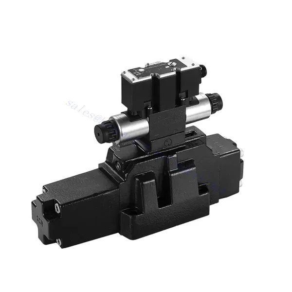
4WRZ/H(E) Series Pilot Operated Proportional Directional Hydraulic Valve
Üheks hüdrosilindrite tootjaks, tarnijaks ja mehaaniliste toodete eksportijaks pakume hüdrosilindreid ja paljusid teisi tooteid.
Palun võtke meiega ühendust üksikasjade saamiseks.
Post:sales@hydraulic-cylinders.net
Tootja tarnija eksportija hüdrosilindrid.
4WRZ/H(E) Series Pilot Operated Proportional Directional Hydraulic Valve
The 4WRZ/H(E) series pilot-operated proportional directional hydraulic valve is a state-of-the-art component designed to provide exceptional precision, control, and efficiency in hydraulic systems. With its advanced pilot-operated proportional control technology, this valve enables accurate flow regulation and seamless directional changes.
The 4WRZ/H(E) series pilot-operated proportional directional hydraulic valve empowers hydraulic systems with precise flow control, versatile directional changes, and energy efficiency. Its pilot-operated proportional control technology ensures accurate and responsive flow adjustment, while the high flow capacity guarantees reliable performance even in demanding applications. By following the recommended usage methods and maintenance guidelines, you can maximize the benefits and longevity of the 4WRZ/H(E) series valve, elevating your hydraulic system to new levels of precision and control. Upgrade your hydraulic setup today and experience the power of the 4WRZ/H(E) series pilot-operated proportional directional hydraulic valve.
4WRZ/H(E) Series Pilot Operated Proportional Directional Hydraulic Valve Key Characteristics:
- Pilot-Operated Proportional Control
- The 4WRZ/H(E) series valve utilizes pilot-operated proportional control technology, allowing precise and proportional flow adjustment based on control signals.
- See funktsioon tagab täpse ja tundliku juhtimise, mille tulemuseks on parem süsteemi jõudlus, väiksem energiatarbimine ja suurem tootlikkus.
- Versatile Directional Control
- See ventiil pakub mitmekülgset hüdraulilise vedeliku suuna juhtimist, mistõttu sobib see laias valikus rakendustes.
- See võimaldab hüdrauliliste komponentide, näiteks silindrite, mootorite ja ajamite sujuvat aktiveerimist ja deaktiveerimist eri suundades, suurendades süsteemi paindlikkust ja kohanemisvõimet.
- High Flow Capacity
- The 4WRZ/H(E) series valve is engineered to handle high flow rates, making it ideal for applications that require substantial hydraulic power.
- Selle vastupidav konstruktsioon tagab usaldusväärse jõudluse isegi nõudlikes tingimustes, pakkudes järjepidevat ja tõhusat vooluhulga juhtimist.
- Energiatõhusus
- By incorporating pilot-operated proportional control, this valve minimizes pressure drops and optimizes energy usage.
- It helps reduce energy consumption, resulting in cost savings and environmental benefits.
4WRZ/H(E) Series Pilot Operated Proportional Directional Hydraulic Valve Parameter:
| GeneraL | |||||||
| Valve type | WRZ | WRZE | |||||
| Paigaldamine | Optional,preferably horizontal | ||||||
| Säilitustemperatuuri vahemik | ℃ | -20 kuni +80 | |||||
| Ümbritseva õhu temperatuuri vahemik | ℃ | -20 kuni +70 | -20 to +50 | ||||
| Kaal | NS 10 | kg | 7.8 | 8 | |||
| NS 16 | kg | 13.4 | 13.6 | ||||
| NS 25 | kg | 18.2 | 18.4 | ||||
| NS 32 | kg | 42.2 | 42.4 | ||||
| Hüdrauliline (measured with HLPAG.p=100bar : 40 ℃ ± 5 ℃) | |||||||
| Suurus | 10 | 16 | 25 | 32 | |||
| Töörõhk | Pilot valve | External pilot oil supply | baar | 30 to 100 bar | |||
| Internal pilot oil supply | baar | 100 to 350 with “D3” only | |||||
| Main valve | baar | to 315 | kuni 350 | kuni 350 | kuni 350 | ||
| Return pressure | Port T (Port R) (external pilot oil drain)) | baar | to 315 | to 250 | to 250 | to 150 | |
| Port T (internal pilot oil drain) | baar | to 30 | to 30 | to 30 | to 30 | ||
| Y-sadam | baar | to 30 | to 30 | to 30 | to 30 | ||
| Pilot oil volume input signal 0- 100 % | cm3 | 1.7 | 4.6 | 10 | 26.5 | ||
| Pilot oil flow in port X and Y with a stepped input signal 0- 100 % | 3.5 | 5.5 | 7 | 15.9 | |||
| Flow of the main valve | L/min | to 170 | to 460 | to 870 | to 1600 | ||
| Hüdrauliline vedelik | L/min | Mineral oil (HL, HLP) to DIN 51524 Further fluids on enquiry | |||||
| Hüdraulikaõli temperatuurivahemik | ℃ | -20 to +80(preferably +40 to +50) | |||||
| Viskoossusvahemik | mm2/s | 20 to 380(preferably 30 to 46) | |||||
| Saastumise aste | Maximum permissible degree of contamination of the pressure fluid is to NAS 1638 or ISO 4406(c) | A filter with a minimum retention rate of βx ≥ 75 is recommended | |||||
| Pilot valve | NAS 1638 class 7 | x=5 | |||||
| Main valve | NAS 1638 class 9 | x=15 | |||||
| Hüsterees | % | ≤6 | |||||
| Elektriline | |||||||
| Valve type | WRZ | WRZE | |||||
| Type of protection of the valve to EN 60529 | IP65 with cable socket mounted and locked | ||||||
| Pinge tüüp | DC | ||||||
| Command value overlap | % | 15 | |||||
| Max. current | A | 1.5 | 2.5 | ||||
| Solenoid coil resisance | Cold value at 20℃ | Ω | 4.8 | 2 | |||
| Maksimaalne soojusväärtus | Ω | 7.2 | 3 | ||||
| Tsükliline kestustegur | % | 100 | |||||
| Mähise temperatuur | ℃ | to 150 | |||||
| Ventiilikaitse vastavalt standardile EN 60529 | IP65 | ||||||
| Control electronics | |||||||
| External amplifier for type WRZ | VT- VSPA2-L2X/… | ||||||
| Käskluse väärtuse signaal | -Voltage input “A1” | V | ±10 | ||||
| –Current input “F1” | mA | 4 to 20 | |||||
4WRZ/H(E) Series Pilot Operated Proportional Directional Hydraulic Valve Advantages:
• Pilot-operated two-stage proportional directional valve, used to control the size and direction of the liquid flow
• Threaded connection type proportional solenoid, the coil can be disassembled separately
• Sub-plate mounting connection structure, connection size conforms to DIN2430 and ISO4401 standards
• Pooli vedru joondamine
• WRZE type with integrated proportional amplifierr
• WRZ type external amplifier (order separately)
Usage Method Of 4WRZ/H(E) Series Pilot Operated Proportional Directional Hydraulic Valve:
- System Evaluation
- Hinnake oma hüdraulikasüsteemi ja tehke kindlaks konkreetsed vooluhulga ja suuna juhtimise nõuded.
- Determine if the 4WRZ/H(E) series valve is suitable based on its flow capacity, pressure rating, and compatibility with your system.
- Valve Selection
- Select the appropriate variant of the 4WRZ/H(E) series valve based on your system parameters, flow requirements, and directional control needs.
- Arvestage selliste teguritega nagu maksimaalne voolukiirus, rõhuklass, reageerimisaeg ja töötingimused.
- Paigaldamine
- Järgige hoolikalt tootja paigaldusjuhiseid, tagades ventiili õige joondamise ja kindla kinnituse.
- Make leak-free connections and ensure the correct flow direction alignment to guarantee optimal performance.
- Control Signal Connection
- Ühendage ventiili juhtsignaali juhtmed sobiva juhtseadmega, näiteks proportsionaalvõimendi või elektroonilise juhtseadmega.
- Täpse ja tundliku juhtimise tagamiseks veenduge ventiili ja juhtseadme õiges juhtmestikus ja ühilduvuses.
How To Bleed Hydraulic Control Valve?
Bleeding a hydraulic control valve is an essential maintenance procedure to remove any trapped air or gas from the system, ensuring optimal performance and efficiency. Here’s a step-by-step guide on how to bleed a hydraulic control valve:
- Süsteemi ettevalmistamine:
- Ensure that the hydraulic system is turned off and that the pressure is relieved. This step is crucial for your safety and to prevent any accidental movement or release of high-pressure fluids.
- Locate the bleeder valve or bleed screw on the hydraulic control valve. It is typically located on the top or side of the valve body and may have a protective cap or cover.
- Positioning and Safety Measures:
- Place a suitable container or absorbent material beneath the bleed valve to catch any fluid that may be expelled during the bleeding process.
- Wear appropriate personal protective equipment (PPE), such as safety goggles and gloves, to protect yourself from hydraulic fluid splashes.
- Opening the Bleed Valve:
- Using an appropriate wrench or tool, carefully loosen the bleed valve or screw counterclockwise. Be cautious not to fully remove it at this stage.
- The bleed valve may have an O-ring or sealing washer. Take note of its position and ensure it is in good condition.
- System Activation:
- Activate the hydraulic system by turning on the power source, such as an engine or hydraulic pump.
- Operate the control mechanism associated with the hydraulic control valve, such as a joystick or lever, to allow fluid flow through the valve.
- Bleeding Process:
- Slowly open the bleed valve by turning it counterclockwise until you start to see hydraulic fluid or air bubbles escaping from the valve.
- Allow the fluid to flow for a few seconds or until you observe a steady stream of fluid without any air bubbles. This indicates that the air has been purged from the system.
- Be cautious not to open the bleed valve too much, as it may lead to excessive fluid loss or system damage.
- Closing the Bleed Valve:
- Once you have successfully bled the system, close the bleed valve by turning it clockwise. Ensure it is tightened securely but avoid over-tightening.
- Check for any leaks around the bleed valve or other connections. If you notice any leaks, address them promptly to prevent further issues.
- System Check:
- Turn off the hydraulic system and inspect the fluid level in the reservoir. Add hydraulic fluid as necessary to maintain the recommended level.
- Test the operation of the hydraulic control valve and associated components to ensure proper functionality.
Tehase võimekus ja suutlikkus:
(1) Kokkupanek
Meil on esmaklassiline sõltumatu teadus- ja arendustegevuse montaažiplatvorm. Hüdrosilindrite tootmistöökojas on neli poolautomaatset tõstesilindrite koosteliini ja üks automaatne kallutussilindrite koosteliin, mille kavandatud aastane tootmisvõimsus on 1 miljon tükki. Spetsiaalsete silindrite töökoda on varustatud erinevate spetsifikatsioonidega poolautomaatse puhastusmontaažisüsteemiga, mille kavandatud aastane tootmisvõimsus on 200 000 ja mis on varustatud kuulsate CNC-töötlemisseadmete, mehaanilise töötlemise keskuse, suure täpsusega silindrite töötlemise eriseadmete, robotkeevitusmasina, automaatse puhastusmasina, automaatse silindri kokkupanemise masina ja automaatse värvimise tootmisliiniga. Olemasolevad kriitilised seadmed rohkem kui 300 komplekti (komplekti). Seadmete ressursside optimaalne jaotamine ja tõhus kasutamine tagavad toodete täpsusnõuded ja vastavad toodete kvaliteedinõuetele.


(2) Töötlemine
Töödeldav töökoda on varustatud kohandatud kallutatud rööpse treipingi keskuse, mehaanilise keskuse, kiire lihvimismasina, keevitusroboti ja muude seotud seadmetega, mis suudavad töödelda silindritorusid, mille maksimaalne siseläbimõõt on 400 mm ja maksimaalne pikkus on 6 meetrit.

(3) Keevitamine

(4) Värvimine ja katmine
Väikese ja keskmise suurusega silindri automaatse veepõhise värvipinnakattega liinide abil, et saavutada automaatne robotlaadimine ja mahalaadimine ning automaatne pihustamine, projekteerimisvõimsus 4000 tükki vahetuse kohta;
Meil on ka poolautomaatne suurte balloonide värvimise tootmisliin, mis töötab jõukettaga ja mille projekteerimisvõimsus on 60 kasti ühe vahetuse kohta.


(5) Testimine
Meil on esmaklassilised kontrolliseadmed ja katsestendid, et tagada silindri jõudlus vastavus nõuetele.

Oleme üks parimaid hüdrosilindrite tootjaid. Pakume laia valikut hüdrosilindreid. Pakume ka vastavaid... põllumajanduslikud käigukastid. Oleme eksportinud oma tooteid klientidele üle maailma ja teeninud hea maine tänu meie suurepärasele tootekvaliteedile ja müügijärgsele teenindusele. Me tervitame kliente kodus ja välismaal, et võtta meiega ühendust, et pidada läbirääkimisi äri, vahetada teavet ja teha meiega koostööd!
Hüdrosilindri kasutamine:
