

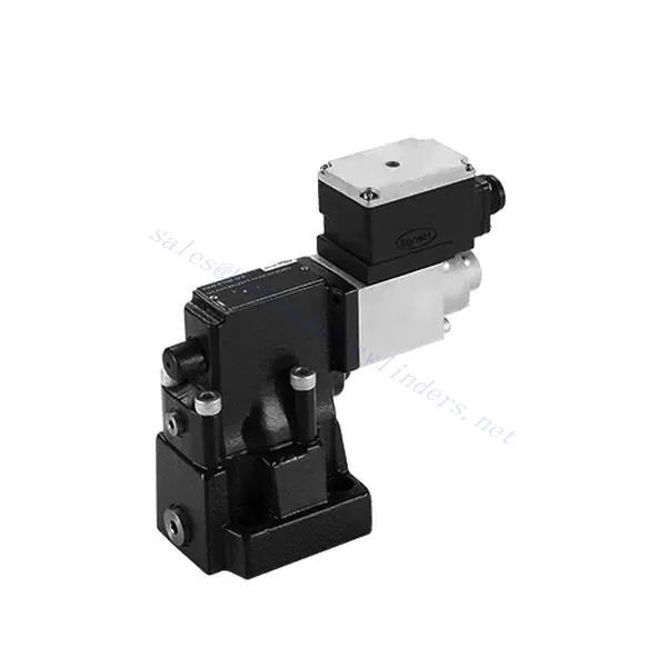
DBE/M(E) Series Proportional Pressure Relief Hydraulic Valve
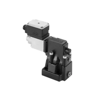

The DBE/M(E) series proportional pressure relief hydraulic valve is a state-of-the-art component designed to deliver precise pressure control in hydraulic systems. With its advanced proportional control technology, this valve ensures optimal performance, efficiency, and safety.
The DBE/M(E) series proportional pressure relief hydraulic valve empowers hydraulic systems with precise pressure control, enhanced efficiency, and equipment protection. With its advanced proportional control technology, this valve ensures optimal performance across various applications. By following the recommended usage methods and maintenance guidelines, you can maximize the benefits and reliability of the DBE/M(E) series valve, elevating the pressure control and overall performance of your hydraulic system. Upgrade your hydraulic setup today and experience superior pressure regulation with the DBE/M(E) series proportional pressure relief hydraulic valve.
DBE6X(E) seeria proportsionaalse rõhuvabastusventiili peamised omadused:
- Proportsionaalne rõhu alandamine:
- The DBE/M(E) series valve offers precise and proportional pressure relief, allowing for dynamic control of hydraulic pressure.
- See tagab täpse rõhu reguleerimise vastavalt muutuvatele koormustingimustele, hoides ära süsteemi ülekoormuse ja kaitstes hüdraulikakomponente.
- Täiustatud süsteemi efektiivsus:
- See ventiil võimaldab täpset hüdraulilise rõhu juhtimist, mille tulemuseks on süsteemi efektiivsuse paranemine ja energiatarbimise vähenemine.
- Soovitud rõhutasemete säilitamisega minimeerib see rõhukõikumisi, optimeerib süsteemi jõudlust ja vähendab tegevuskulusid.
- Ohutus ja seadmete kaitse:
- The DBE/M(E) series valve acts as a protective mechanism by limiting the pressure within the hydraulic system, safeguarding equipment and operators.
- See hoiab ära liigse rõhu tekkimise, vähendades komponentide kahjustumise, süsteemi rikete ja võimalike õnnetuste ohtu.
- Proportsionaalse juhtimise funktsionaalsus:
- With its proportional control technology, the DBE/M(E) series valve offers smooth and precise pressure adjustment.
- See võimaldab reaalajas rõhu juhtimist, mis tagab sujuva integreerimise erinevatesse hüdraulikasüsteemidesse ja rakendustesse.
DBE/M(E) Series Proportional Pressure Relief Hydraulic Valve Parameter:
| Üldine | ||||
| Vedelik | NBR- ja FKM-tihenditele sobiv mineraalõli | |||
| Fosfaatestrid FKM-tihendi jaoks | ||||
| Vedeliku temperatuurivahemik | ℃ | -30 kuni +80 (NBR-tihendid) | ||
| -20 kuni +80 (FKM tihendid) | ||||
| Viskoossusvahemik | mm2/s | 2,8 kuni 380 | ||
| Saastumise aste | Vedeliku maksimaalne lubatud saastumisaste: klass 9. NAS 1638 või 20/18/15, ISO4406 | |||
| Maksimaalne töörõhk | 315 baari | |||
| Port A, B, X | baar | 50; 100; 200; 315 | ||
| Maksimaalne seadistusrõhk | baar | Vt vooluhulga (Q) kohta karakteristikuid | ||
| Min. seadistatav rõhk | =Minimaalne seadistatav rõhk | |||
| Min. seadistatav rõhk 0-käsuväärtuse juures | Eraldi ja nullrõhu all mahutitesse | |||
| Tagasivooluõli rõhuport Y | baar | Rõhu seadistamine | Rõhuvahemik maksimaalse ohutusrõhu all | |
| Maksimaalne rõhuohutus (lõpmatult reguleeritav) | 50 baari | 10-60+20 baar | ||
| 100 baari | 10-120+20 baar | |||
| 200 baari | 10-220+20 baar | |||
| 315 baari | 10-340+20 baar | |||
| Maksimaalse rõhu ohutusseadistuse tingimus | When rated pressure is 50 bar, between 60 bar and 80 bar | |||
| When rated pressure is 100 bar, between120 bar and 140 bar | ||||
| When rated pressure is 200 bar, between 220 bar and 240 bar | ||||
| When rated pressure is 315 bar, between 340 bar and 360 bar | ||||
| Suurus | 10 | 25 | 32 | |
| Maksimaalne voolukiirus | 200 | 400 | 600 | |
| Pilootõli (pilootventiili jaoks)) | L/min | 0,7 kuni 2 | ||
| Lineaarsus | L/min | ±3,5% | ||
| Korduvus | <±2% | |||
| Hüsterees | shimmi abil | ilma shimmita | ||
| ±1,5% P max (200 Hz, amplituud 200 mAss) | ±4,5% P max | |||
| Lülitusaeg | 30~150ms(independent with the system) | |||
| Elektrilised andmed | ||||
| Võimsus | DC | |||
| Min solenoidi vool | mA | 100 | ||
| Maksimaalne solenoidvool | mA | 800 | ||
| Mähise takistus | 19.5Ω at 20℃, Max. warm value: 28.8Ω | |||
| Tööstaatus | Pidev | |||
| Maksimaalne ümbritseva õhu temperatuuri vahemik | +50 ℃ | |||
| Elektriühendus | Pistikühendus DIN 43 650/2 +SL/PG11 järgi | |||
| Isolatsioon vastavalt standardile DIN 40 050 | IP65 | |||
| Amplifier | VT2000 | |||
DBE/M(E) Series Proportional Pressure Relief Hydraulic Valve Advantages:
• Kasutatakse alumise alusplaadi paigaldamiseks
• Paigalduspind vastab standarditele DIN24340 E ja ISO 6264
• Kasutatakse õliteede plokkide paigaldamisel
• Neli rõhuvahemikku
• Kõrgeima rõhu kaitsekonstruktsioon (valikuline)
• Sobiv elektrooniline võimendi VT-2000 tüüp (tuleb eraldi tellida)
Usage Method Of DBE/M(E) Series Proportional Pressure Relief Hydraulic Valve:
- Süsteemi hindamine:
- Hinnake oma hüdraulikasüsteemi ja tehke kindlaks spetsiifilised rõhu reguleerimise nõuded.
- Determine if the DBE/M(E) series valve is compatible with your system based on its pressure range, flow capacity, and other specifications.
- Ventiili valik:
- Choose the appropriate DBE/M(E) series valve variant based on your system parameters, pressure range, and flow requirements.
- Arvestage maksimaalse rõhuklassiga, reageerimisajaga ja töötingimustega.
- Paigaldamine:
- Follow the manufacturer’s installation instructions carefully, ensuring proper alignment and secure valve mounting.
- Ühendage ventiil hüdrosüsteemiga, tagades lekkevabad ühendused ja õige voolusuuna joondamise.
- Rõhu reguleerimine:
- Utilize the proportional control signal or adjustment mechanism provided with the DBE/M(E) series valve to set the desired pressure relief level.
- Täpse rõhu reguleerimise saavutamiseks reguleerige ventiili sammhaaval, jälgides manomeetri näitu ja süsteemi reaktsiooni.
How To Adjust Hydraulic Pressure Relief Valve?
Adjusting a hydraulic pressure relief valve allows you to regulate the maximum pressure within a hydraulic system. This is important for maintaining system integrity and preventing damage to components. Here’s a step-by-step guide on how to adjust a hydraulic pressure relief valve:
- Surveventiili tuvastamine:
- Locate the hydraulic pressure relief valve in your system. It is typically positioned in the hydraulic line or integrated into a manifold block.
- Mõista ventiili konstruktsiooni:
- Tutvuge kasutatava ülerõhuventiili konkreetse konstruktsiooniga. Erinevatel ventiilidel võivad olla erinevad reguleerimismehhanismid, näiteks nupp, kruvi või lukustusmutter.
- Determine the Desired Pressure Setting:
- Assess the requirements of your hydraulic system and determine the desired maximum pressure. Consider the system’s specifications, load conditions, and safety limits.
- Süsteemi ettevalmistamine:
- Before making any adjustments, shut off the hydraulic system and relieve the pressure by moving the control levers back and forth or following the manufacturer’s recommended procedure.
- Leidke reguleerimismehhanism:
- Tuvastage ülerõhuventiili reguleerimismehhanism. See võib olla nupp, kruvi või lukustusmutter, mis asub ventiili korpusel või selle kõrval.
- Reguleerige ventiili:
- If the valve has a knob or handle, turn it clockwise to increase the pressure relief setting or counterclockwise to decrease it. If the valve has a screw, turn it clockwise to increase the ground or counterclockwise to drop it.
- Tehke järkjärgulisi kohandusi:
- When adjusting the pressure relief valve, make small, incremental changes to avoid sudden or drastic variations in pressure. This allows you to fine-tune the system and prevent potential damage.
- Jälgige süsteemi:
- With each adjustment, observe the hydraulic system’s pressure gauge or indicator to see the effect of the changes. Ensure that the pressure stays within the desired range.
- Testi ja kinnita:
- Gradually increase the system’s pressure and monitor the pressure relief valve’s response. Ensure it relieves stress when the maximum set pressure is reached and maintains the desired maximum pressure.
- Lukusta reguleerimine:
- Once you have achieved the desired pressure setting, secure the adjustment mechanism to prevent unintended changes. Some valves may have a locking nut or set screw that can be tightened to hold the adjustment in place.
- Document the Adjustment:
- Keep a record of the adjusted pressure relief setting for future reference and maintenance purposes. This documentation will help maintain consistency and aid troubleshooting efforts.
Tehase võimekus ja suutlikkus:
(1) Kokkupanek
Meil on esmaklassiline sõltumatu teadus- ja arendustegevuse montaažiplatvorm. Hüdrosilindrite tootmistöökojas on neli poolautomaatset tõstesilindrite koosteliini ja üks automaatne kallutussilindrite koosteliin, mille kavandatud aastane tootmisvõimsus on 1 miljon tükki. Spetsiaalsete silindrite töökoda on varustatud erinevate spetsifikatsioonidega poolautomaatse puhastusmontaažisüsteemiga, mille kavandatud aastane tootmisvõimsus on 200 000 ja mis on varustatud kuulsate CNC-töötlemisseadmete, mehaanilise töötlemise keskuse, suure täpsusega silindrite töötlemise eriseadmete, robotkeevitusmasina, automaatse puhastusmasina, automaatse silindri kokkupanemise masina ja automaatse värvimise tootmisliiniga. Olemasolevad kriitilised seadmed rohkem kui 300 komplekti (komplekti). Seadmete ressursside optimaalne jaotamine ja tõhus kasutamine tagavad toodete täpsusnõuded ja vastavad toodete kvaliteedinõuetele.


(2) Töötlemine
Töödeldav töökoda on varustatud kohandatud kallutatud rööpse treipingi keskuse, mehaanilise keskuse, kiire lihvimismasina, keevitusroboti ja muude seotud seadmetega, mis suudavad töödelda silindritorusid, mille maksimaalne siseläbimõõt on 400 mm ja maksimaalne pikkus on 6 meetrit.


(3) Keevitamine


(4) Värvimine ja katmine
Väikese ja keskmise suurusega silindri automaatse veepõhise värvipinnakattega liinide abil, et saavutada automaatne robotlaadimine ja mahalaadimine ning automaatne pihustamine, projekteerimisvõimsus 4000 tükki vahetuse kohta;
Meil on ka poolautomaatne suurte balloonide värvimise tootmisliin, mis töötab jõukettaga ja mille projekteerimisvõimsus on 60 kasti ühe vahetuse kohta.


(5) Testimine
Meil on esmaklassilised kontrolliseadmed ja katsestendid, et tagada silindri jõudlus vastavus nõuetele.


Oleme üks parimaid hüdrosilindrite tootjaid. Pakume laia valikut hüdrosilindreid. Pakume ka vastavaid... põllumajanduslikud käigukastid. Oleme eksportinud oma tooteid klientidele üle maailma ja teeninud hea maine tänu meie suurepärasele tootekvaliteedile ja müügijärgsele teenindusele. Me tervitame kliente kodus ja välismaal, et võtta meiega ühendust, et pidada läbirääkimisi äri, vahetada teavet ja teha meiega koostööd!