KSF seeria hüdrauliline ventiil
Üheks hüdrosilindrite tootjaks, tarnijaks ja mehaaniliste toodete eksportijaks pakume hüdrosilindreid ja paljusid teisi tooteid.
Palun võtke meiega ühendust üksikasjade saamiseks.
Post:sales@hydraulic-cylinders.net
Tootja tarnija eksportija hüdrosilindrid.
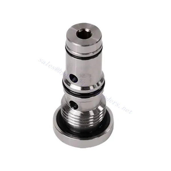
KSF seeria hüdrauliline ventiil
The KSF series shuttle hydraulic valve is a high-performance component designed to enhance fluid flow control in hydraulic systems. With its advanced design and robust construction, this valve offers precise and reliable operation, ensuring optimal system performance.
The KSF series shuttle hydraulic valve is an exceptional solution for fluid flow control in hydraulic systems. With its shuttle valve functionality, robust construction, high flow capacity, and compact design, this valve optimizes performance and ensures efficient utilization of hydraulic power. By following the recommended usage methods and maintenance practices, the KSF series shuttle hydraulic valve delivers reliable operation and extends the lifespan of hydraulic systems. Upgrade your hydraulic system with the KSF series shuttle hydraulic valve and experience enhanced fluid flow control for improved overall system performance.
KSF Series Shuttle Hydraulic Valve Key Characteristics:
- Shuttle Valve Functionality:
- The KSF series valve incorporates a shuttle valve design to divert hydraulic fluid flow between two circuits.
- It enables the selection of the circuit with higher pressure, ensuring efficient utilization of hydraulic power and preventing pressure imbalances.
- Vastupidav konstruktsioon:
- Built with durable materials, the KSF series shuttle hydraulic valve is designed to withstand high-pressure environments and demanding operating conditions.
- Its robust construction ensures longevity and reliability, minimizing downtime and maintenance costs.
- Suur läbilaskevõime:
- The KSF series valve offers a high flow capacity, allowing for efficient transfer of hydraulic fluid between circuits.
- It minimizes pressure drops, ensuring maximum power delivery and system performance.
- Compact and Versatile Design:
- The valve’s compact design makes it suitable for installations with limited space or weight constraints.
- Its versatility allows easy integration into various hydraulic systems, including industrial machinery, mobile equipment, and power units.
KSF Series Shuttle Hydraulic Valve Parameter:
| Suurus | NG6 | NG10 | |
| Vedeliku temperatuurivahemik | ℃ | -30 to +80 (NBR seals) | |
| -20 kuni +80 (FKM tihendid) | |||
| Viskoossusvahemik | mm2/s | Recommandation 30~80, permission 20~380 | |
| Maksimaalne töörõhk | baar | 350 | |
| Maksimaalne voolukiirus | L/min | 40 | 60 |
| Kaal | kg | 0.5 | 0.8 |
| Vedelik | NBR- ja FKM-tihenditele sobiv mineraalõli | ||
| Fosfaatestrid FKM-tihendi jaoks | |||
| Saastumise aste | Vedeliku maksimaalne lubatud saastumisaste: klass 9. NAS 1638 või 20/18/15, ISO4406 | ||
KSF Series Shuttle Hydraulic Valve Advantages:
• Seal without leakage
• Cartridge structure for oil block installation
Usage Method Of KSF Series Shuttle Hydraulic Valve:
- Süsteemianalüüs:
- Before installation, perform a comprehensive hydraulic system analysis to determine specific requirements and operating parameters.
- Consider factors such as flow rates, pressure ratings, and compatibility with the KSF series shuttle hydraulic valve.
- Ventiili valik:
- Choose the appropriate KSF series valve variant based on the system’s requirements and specifications.
- Consider factors like flow capacity, pressure ratings, and compatibility with other system components.
- Paigaldamine:
- Follow the manufacturer’s instructions for properly installing the KSF series shuttle hydraulic Valve in the hydraulic system.
- Ensure a secure fit, proper alignment with the fluid flow path, and adequate sealing to prevent leaks.
- Circuit Connection:
- Connect the inlet and outlet ports of the valve to the corresponding circuits that require fluid diversion.
- Ensure proper identification and connection of the high-pressure circuit and low-pressure circuit.
How Does A Hydraulic Flow Control Valve Work?
A hydraulic flow control valve is a device used to regulate and control the speed of hydraulic fluid within a hydraulic system. It allows the operator to adjust the flow rate of the liquid, thereby preventing the speed of hydraulic actuators or controlling the rate of energy transfer. Here’s an explanation of how a hydraulic flow control valve works:
- Ventiili struktuur:
- A hydraulic flow control valve typically consists of a valve body with inlet and outlet ports, a movable spool or poppet, and an actuating mechanism.
- The valve body contains internal passages and chambers that control the flow of hydraulic fluid.
- Vedeliku vooluteed:
- The flow control valve has an inlet port that connects to the hydraulic power source, such as a pump, and an outlet port that connects to the hydraulic actuator or another component.
- The valve provides different flow paths for fluid, allowing it to be controlled and regulated.
- Spool or Poppet:
- The valve body houses a movable spool or poppet that regulates the flow of hydraulic fluid.
- The spool can slide within the valve body, while the poppet can move linearly or rotate to open or close specific passages.
- Actuating Mechanism:
- Hydraulic flow control valves can be actuated manually, electrically, or through other means, depending on the specific design and application requirements.
- Manual actuation involves adjusting a handle, knob, or lever to position the spool or poppet.
- Electrical actuation utilizes solenoids that receive electrical signals to shift the spool or poppet, allowing for remote control and automation.
- Ventiili asendid:
- A hydraulic flow control valve typically has multiple positions that the spool or poppet can assume, each corresponding to a specific flow rate.
- The valve may have a range of preset positions or offer continuous adjustment for fine-tuning the flow rate.
- As the spool or poppet shifts, it aligns with specific passages, opening or closing them to control the fluid flow.
- Flow Regulation:
- By adjusting the position of the spool or poppet, the operator can control the size of the flow passages, thereby regulating the flow rate of the hydraulic fluid.
- When the passages are fully open, the fluid flows freely, allowing for maximum flow rate.
- Partially closing the passages restricts the flow, reducing the flow rate and controlling the speed of hydraulic actuators.
- Rõhu kompenseerimine:
- Some hydraulic flow control valves incorporate pressure compensation mechanisms to maintain a consistent flow rate despite changes in system pressure.
- These mechanisms ensure that the desired flow rate is maintained even when the system encounters variations in load or pressure.
Tehase võimekus ja suutlikkus:
(1) Kokkupanek
Meil on esmaklassiline sõltumatu teadus- ja arendustegevuse montaažiplatvorm. Hüdrosilindrite tootmistöökojas on neli poolautomaatset tõstesilindrite koosteliini ja üks automaatne kallutussilindrite koosteliin, mille kavandatud aastane tootmisvõimsus on 1 miljon tükki. Spetsiaalsete silindrite töökoda on varustatud erinevate spetsifikatsioonidega poolautomaatse puhastusmontaažisüsteemiga, mille kavandatud aastane tootmisvõimsus on 200 000 ja mis on varustatud kuulsate CNC-töötlemisseadmete, mehaanilise töötlemise keskuse, suure täpsusega silindrite töötlemise eriseadmete, robotkeevitusmasina, automaatse puhastusmasina, automaatse silindri kokkupanemise masina ja automaatse värvimise tootmisliiniga. Olemasolevad kriitilised seadmed rohkem kui 300 komplekti (komplekti). Seadmete ressursside optimaalne jaotamine ja tõhus kasutamine tagavad toodete täpsusnõuded ja vastavad toodete kvaliteedinõuetele.


(2) Töötlemine
Töödeldav töökoda on varustatud kohandatud kallutatud rööpse treipingi keskuse, mehaanilise keskuse, kiire lihvimismasina, keevitusroboti ja muude seotud seadmetega, mis suudavad töödelda silindritorusid, mille maksimaalne siseläbimõõt on 400 mm ja maksimaalne pikkus on 6 meetrit.

(3) Keevitamine

(4) Värvimine ja katmine
Väikese ja keskmise suurusega silindri automaatse veepõhise värvipinnakattega liinide abil, et saavutada automaatne robotlaadimine ja mahalaadimine ning automaatne pihustamine, projekteerimisvõimsus 4000 tükki vahetuse kohta;
Meil on ka poolautomaatne suurte balloonide värvimise tootmisliin, mis töötab jõukettaga ja mille projekteerimisvõimsus on 60 kasti ühe vahetuse kohta.


(5) Testimine
Meil on esmaklassilised kontrolliseadmed ja katsestendid, et tagada silindri jõudlus vastavus nõuetele.

Oleme üks parimaid hüdrosilindrite tootjaid. Pakume laia valikut hüdrosilindreid. Pakume ka vastavaid... põllumajanduslikud käigukastid. Oleme eksportinud oma tooteid klientidele üle maailma ja teeninud hea maine tänu meie suurepärasele tootekvaliteedile ja müügijärgsele teenindusele. Me tervitame kliente kodus ja välismaal, et võtta meiega ühendust, et pidada läbirääkimisi äri, vahetada teavet ja teha meiega koostööd!
Hüdrosilindri kasutamine:
