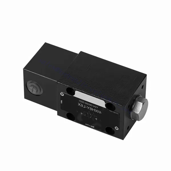
WH(D) Series Directional Hydraulic Valve With Fluidic Actuation
Üheks hüdrosilindrite tootjaks, tarnijaks ja mehaaniliste toodete eksportijaks pakume hüdrosilindreid ja paljusid teisi tooteid.
Palun võtke meiega ühendust üksikasjade saamiseks.
Post:sales@hydraulic-cylinders.net
Tootja tarnija eksportija hüdrosilindrid.
WH(D) Series Directional Hydraulic Valve With Fluidic Actuation
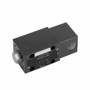
The WH(D) series directional hydraulic valve with fluidic actuation is a state-of-the-art product designed to provide precise control and efficient operation in hydraulic systems. With its advanced features and reliable performance, this valve offers enhanced functionality and versatility.
The WH(D)series directional hydraulic valve with fluidic actuation offers advanced control and efficiency for hydraulic systems. Its fluidic actuation mechanism, precise directional control, and high flow capacity enhance functionality and versatility. Following the recommended usage methods and adhering to regular maintenance practices, the WH(D) series valve will continue delivering efficient and reliable operation. Upgrade your hydraulic system with the WH(D) series directional hydraulic valve and experience the benefits of enhanced control and efficiency.
WH(D) Series Directional Hydraulic Valve With Fluidic Actuation Key Characteristics:
- Fluidic Actuation:
- The WH(D) series valve utilizes fluidic actuation, allowing for precise and responsive fluid flow control within hydraulic systems.
- This actuation method offers improved accuracy and efficiency compared to traditional mechanisms.
- Suunakontroll:
- This hydraulic valve enables precise directional control of fluid flow, allowing operators to select the desired flow path easily.
- Directing the hydraulic fluid to the appropriate actuators or components ensures efficient and reliable operation.
- Suur läbilaskevõime:
- The WH(D) Series Valve is designed to handle high flow rates, making it suitable for applications that require substantial fluid flow.
- Its robust construction and optimized internal passages ensure smooth flow and minimal pressure drop.
- Mitmekülgsus:
- This valve is highly versatile and can be used in various industries and applications, such as manufacturing, construction, agriculture, etc.
- It can be integrated into hydraulic systems that require precise control and efficient fluid management.
WH(D) Series Directional Hydraulic Valve With Fluidic Actuation Parameter:
NG6
| Paigaldusasend | Valikuline | ||
| Vedeliku temperatuurivahemik | ℃ | -30 kuni +80 (NBR-tihendid) | |
| -20 kuni +80 (FKM tihendid) | |||
| Port Max. töörõhk | Port ABP | baar | 315 |
| Sadam T | baar | 60 | |
| Maksimaalne voolukiirus | L/min | 60 | |
| Voolu ristlõige (neutraalse asendi lülitamine) | Q-tüüp | mm2 | Sümboli Q puhul on nimiristlõige 6% |
| W-tüüp | mm2 | Sümboli W puhul nimiristlõike 3% | |
| Vedelik | Mineraalõli; fosfaatester | ||
| Viskoossusvahemik | mm2/s | 2,8 kuni 500 | |
| Saastumise aste | Vedeliku maksimaalne lubatud saastumisaste: klass 9. NAS 1638 või 20/18/15, ISO4406 | ||
| Kaal | kg | 1.4 | |
NG10
| Paigaldusasend | Valikuline | ||
| Vedeliku temperatuurivahemik | ℃ | -30 kuni +80 (NBR-tihendid) | |
| -20 kuni +80 (FKM tihendid) | |||
| Port Max. töörõhk | Port ABP | baar | 315 |
| Sadam T | baar | 60 | |
| Maksimaalne voolukiirus | L/min | 120 | |
| Voolu ristlõige (neutraalse asendi lülitamine) | V-tüüpi | mm2 | 11(A/B → T); 10,3(P → A/B) |
| W-tüüp | mm2 | 2,5 (A/B → T) | |
| Q-tüüp | mm2 | 5,5 (A/B → T) | |
| Vedelik | Mineraalõli; fosfaatester | ||
| Viskoossusvahemik | mm2/s | 2,8 kuni 500 | |
| Saastumise aste | Vedeliku maksimaalne lubatud saastumisaste: klass 9. NAS 1638 või 20/18/15, ISO4406 | ||
| Kaal | kg | 4 | |
WH(D) Series Directional Hydraulic Valve With Fluidic Actuation Advantages:
• Otsetoimeline suunaventiil otsetoimeline suunaventiil
• Scroll wheel can rotate 90°
• Nineteen standard slide valve functions
Usage Method Of WH(D) Series Directional Hydraulic Valve With Fluidic Actuation:
- Süsteemi integreerimine:
- Identify the optimal location for the WH(D) series valve within the hydraulic system, considering the desired flow path and control requirements.
- Veenduge, et see vastaks süsteemi rõhu- ja vooluspetsifikatsioonidele.
- Paigaldage ventiil kindlalt sobivate klambrite või kinnitustarvikute abil.
- Vedelikuühendused:
- Valige turvaliste ja lekkevabade ühenduste tagamiseks ühilduvad hüdraulilised liitmikud ja voolikud.
- Paigaldamise ajal järgige tootja juhiseid õigete pöördemomentide väärtuste kohta.
- Usaldusväärse tihenduse tagamiseks kasutage sobivaid keermetihendeid või teipi.
- Actuation:
- Familiarize yourself with the fluidic actuation mechanism of the valve and understand the control methods available.
- Connect the actuation lines to the designated ports, ensuring proper identification and connection integrity.
- Juhtimine ja reguleerimine:
- Employ the recommended control method, such as manual levers, solenoid valves, or other actuation devices, to operate the WH(D) Series Valve.
- Adjust the valve settings according to the desired flow direction and flow rates, ensuring optimal performance.
How A Hydraulic Valve Works?
A hydraulic valve is a critical component in a hydraulic system that controls the flow and direction of hydraulic fluid. It allows operators to regulate the movement and pressure of the liquid, enabling precise control over various hydraulic functions. Here’s a simplified explanation of how a hydraulic valve works:
- Ventiili struktuur:
- A hydraulic valve typically consists of a valve body, which houses various internal components such as ports, chambers, and passages.
- The valve body also contains movable parts, such as spools or poppets, which control the flow of hydraulic fluid.
- Vedeliku vool:
- Hydraulic valves have multiple ports that connect to different sections of the hydraulic system.
- The hydraulic fluid enters the valve through an inlet port and flows through internal passages within the valve body.
- Pooli või nuga liikumine:
- A spool or poppet mechanism controls the movement of the hydraulic valve.
- The spool is a cylindrical component with lands or grooves machined into its surface, while a poppet is a movable plug-like element.
- When the spool or poppet is in a specific position, it allows hydraulic fluid to flow through certain passages and blocks others.
- Ventiili käivitamine:
- Hydraulic valves can be actuated in various ways, such as manual levers, solenoids, or pilot control.
- Actuation mechanisms control the position of the spool or poppet, determining which passages are opened or closed.
- Manual valves are operated by hand, while solenoid valves use an electrical signal to move the spool or poppet.
- Flow Direction and Control:
- By adjusting the position of the spool or poppet, hydraulic valves can control the direction of fluid flow.
- For example, in a directional control valve, the spool’s position determines whether fluid flows from the inlet to the outlet or is redirected to other ports.
- Other hydraulic valves, such as pressure control or flow control valves, regulate the fluid pressure or flow rate respectively.
- Rõhu kompenseerimine:
- Hydraulic valves often incorporate pressure compensation mechanisms to maintain a consistent pressure within the system.
- These mechanisms ensure that the valve adjusts to changes in pressure and maintains the desired flow rate or pressure level.
- Return or Exhaust:
- In some hydraulic systems, valves provide a return or exhaust path for hydraulic fluid.
- These valves enable the controlled release or redirection of fluid back to the reservoir when it is no longer required in a particular circuit.
Tehase võimekus ja suutlikkus:
(1) Kokkupanek
Meil on esmaklassiline sõltumatu teadus- ja arendustegevuse montaažiplatvorm. Hüdrosilindrite tootmistöökojas on neli poolautomaatset tõstesilindrite koosteliini ja üks automaatne kallutussilindrite koosteliin, mille kavandatud aastane tootmisvõimsus on 1 miljon tükki. Spetsiaalsete silindrite töökoda on varustatud erinevate spetsifikatsioonidega poolautomaatse puhastusmontaažisüsteemiga, mille kavandatud aastane tootmisvõimsus on 200 000 ja mis on varustatud kuulsate CNC-töötlemisseadmete, mehaanilise töötlemise keskuse, suure täpsusega silindrite töötlemise eriseadmete, robotkeevitusmasina, automaatse puhastusmasina, automaatse silindri kokkupanemise masina ja automaatse värvimise tootmisliiniga. Olemasolevad kriitilised seadmed rohkem kui 300 komplekti (komplekti). Seadmete ressursside optimaalne jaotamine ja tõhus kasutamine tagavad toodete täpsusnõuded ja vastavad toodete kvaliteedinõuetele.


(2) Töötlemine
Töödeldav töökoda on varustatud kohandatud kallutatud rööpse treipingi keskuse, mehaanilise keskuse, kiire lihvimismasina, keevitusroboti ja muude seotud seadmetega, mis suudavad töödelda silindritorusid, mille maksimaalne siseläbimõõt on 400 mm ja maksimaalne pikkus on 6 meetrit.

(3) Keevitamine

(4) Värvimine ja katmine
Väikese ja keskmise suurusega silindri automaatse veepõhise värvipinnakattega liinide abil, et saavutada automaatne robotlaadimine ja mahalaadimine ning automaatne pihustamine, projekteerimisvõimsus 4000 tükki vahetuse kohta;
Meil on ka poolautomaatne suurte balloonide värvimise tootmisliin, mis töötab jõukettaga ja mille projekteerimisvõimsus on 60 kasti ühe vahetuse kohta.


(5) Testimine
Meil on esmaklassilised kontrolliseadmed ja katsestendid, et tagada silindri jõudlus vastavus nõuetele.

Oleme üks parimaid hüdrosilindrite tootjaid. Pakume laia valikut hüdrosilindreid. Pakume ka vastavaid... põllumajanduslikud käigukastid. Oleme eksportinud oma tooteid klientidele üle maailma ja teeninud hea maine tänu meie suurepärasele tootekvaliteedile ja müügijärgsele teenindusele. Me tervitame kliente kodus ja välismaal, et võtta meiega ühendust, et pidada läbirääkimisi äri, vahetada teavet ja teha meiega koostööd!
Hüdrosilindri kasutamine:
